-
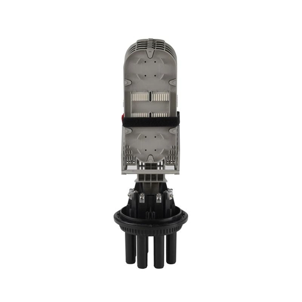
Comparison of High Temperature Resistance of Optical Splitter Boxes and Performance vs Copper Cables
We'll explore thermal limits for different fiber types, explain how temperature affects fiber performance, break down application-specific thermal challenges, and provide actionable tips for choosing the right temperature-resilient fiber. Optical fiber's ability to withstand extreme heat and cold directly impacts signal integrity, network reliability, and maintenance costs, especially in harsh environments like industrial facilities, outdoor installations, and data centers. Laboratory accelerated aging environments have long been used as a measure to predict field performance of optical fiber and cables'. Copper and fiber optic cables each offer distinct advantages and disadvantages that can impact performance, cost, and long-term efficiency. “Copper cables have traditionally served most network links between servers, routers, and switches,” explained. Many engineers struggle with performance drops in high-temperature environments. Harsh heat can degrade normal fiber optic cables, causing downtime, data loss, or expensive replacements.
[PDF Version]
-
Long-distance optical transceivers with low loss 2026 model CE certified
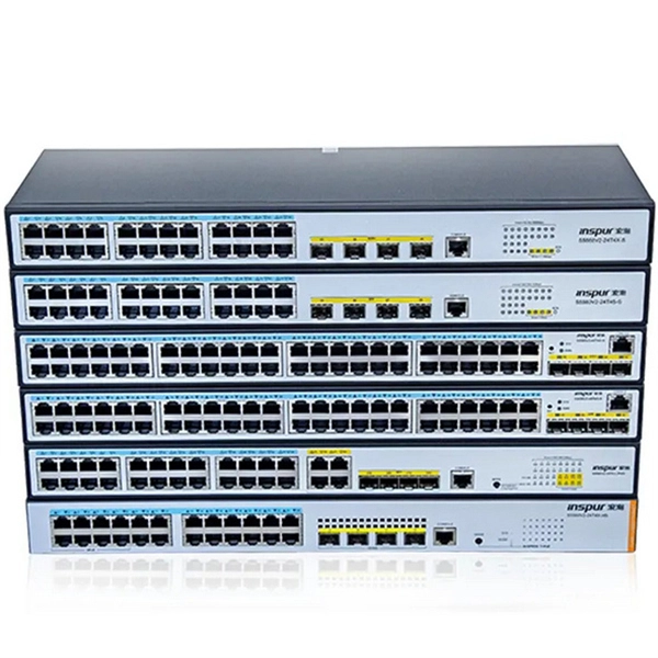
Explore the critical role of telecom grade C-band transceivers in long-distance optical transmission, with specs, deployment insights, and expert guidance. Compared with 850nm or 1310nm SFP modules, 1550nm SFPs are designed for scenarios where signal attenuation, link budget. In the modern network, transceivers are categorized primarily by their reach (distance) and media type (Multimode vs. Miscalculating these distances leads to bit errors and link failures that can cripple a mission-critical environment. Hyperscale Data Centers: High-density spine-leaf. In the rapidly evolving landscape of hyperscale data centers, 5G Open-RAN architectures, and enterprise campus backbones, the optical transceiver has graduated from a commodity component to a critical strategic asset. From short-reach SR4 (hundreds of meters) to intermediate-reach LR4 (up to 10 kilometers), and further to. The Innoptical's IN-C2DCO-200G-LH coherent module, utilizes a trio of indium phosphide (InP) based PICs, covering the laser, modulation, and receiver functions. Through integration, we have enabled almost complete on-wafer test of our PICs. We have a FAE team to provide tailor-made network.
[PDF Version]
-
Method of Hanging Aerial Optical Cables
Many people are confused about the hanging of aerial optical cables. In fact, there are two methods for aerial optical cables laying: one is "fixed-pulley traction method", including "manual traction method" and "mechanical traction method"; the other is "cable tray moving and releasing method". The methods described are intended for guideline use only, as it is impossible to cover all the various conditions that may arise during an installation. Individual company practices for placing. Aerial Cable Installation Deploying fiber above ground on poles or towers removes the need for underground digging and is particularly useful when the ground is uneven, rocky or both. Loads that exceed the ratings may increase attenuation in the fibres up to the point of. Many different methods are used for cable installation. Failure to do so can result in life-threat t truck or on a ladder so that it cannot fall. Materials and equipment should not unnec lled for in your company's safety proced s and, if necessary, lineman's rubber gloves. Use the leather gloves when.
[PDF Version]
-
Standard for Burial Depth of Telecommunication Optical Cables
The International Telecommunication Union (ITU) and Institute of Electrical and Electronics Engineers (IEEE) recommend a minimum depth of 0. 6 meters for urban areas and 1. 0 meters for rural or agricultural zones to protect against frost, plows, and erosion. 0 meters for rural. The short answer, based on general industry standards and the National Electrical Code (NEC), is that fiber optic cable is typically buried between 24 inches (60 cm) and 30 inches (76 cm) deep. However, simply hitting this depth isn't enough to guarantee your network survives. 8 million km in scope by 2025 (per TeleGeography), burying these cords of light comes with the benefits of avoiding cable damage, decreasing downtime, and extending their operational lifetime. In high-load areas such as roads or backbone routes, burial depth can reach 48 inches (120 cm) or more. This guide provides a comprehensive overview of industry.
[PDF Version]
-
Do optical cables necessarily require thermal fusion
The basic difference between the two methods is simple: with fusion splicing, the fibres are melted and fused (welded) together, creating a permanent connection, whereas with mechanical Splicing, they are aligned and clamped together using an adhesive (not melted). In practice, most fibre terminations are done using either fusion Splicing or mechanical Splicing. Both techniques serve the purpose of joining optical fibers, but they differ in terms of their processes and advantages. In this post, we will delve. In fact, many integrators have standardized on universal fiber cables with plenum indoor/outdoor ratings for both residential and commercial prewires thanks to trade costs starting at $0. 05 dB, while mechanical splicing uses alignment fixtures with index-matching gel, typically producing.
[PDF Version]
-
How to make optical fiber cables using an optical fiber polishing machine
Learn how to polish fiber optic patch cord step-by-step. Includes preparation, polishing process, precautions, and end-face inspection for high-quality results. It discusses the cases where polishing is superior to cleaving of fibers, for example, for achieving precise end angles. Thorlabs offers a family of products to assist customers who would like to terminate their bare fiber, including fiber polishing film for use with ceramic or stainless steel ferrules, polishing pucks, polishing plates, and termination kits. We also offer instructions on how to polish a connector. How to Make High-Quality Fiber Optic Patch Cord? – Polishing Prepare Tools and Consumables: Polish Machine, Polish Pad, Polish Film, Polish Jig, Polish Oil, Fiber Cutting Pen 1. Cutting Fiber After removing the ferrule from the oven, use a fan to blow the ferrule to cool it down.
[PDF Version]
-
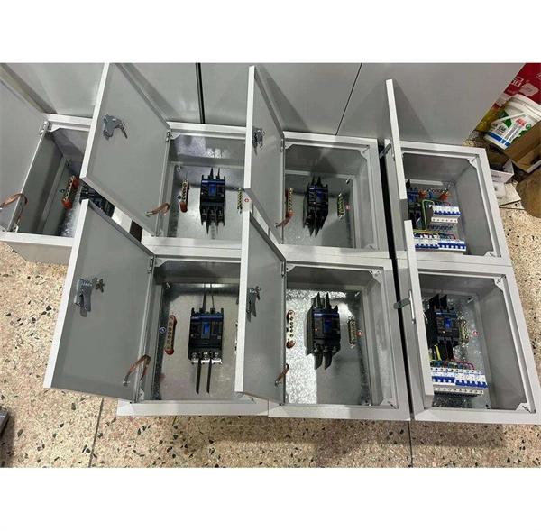
Optical cables and electrical cables share the same cable trench
The subcontractor will generally install just the conduit for these utilities, and then the utility companies will then pull their own cable through after. 8208 Change list- The following is a list of Decisions and Resolutions which authorized statewide general changes to this Order, applicable to all operators of underground systems. Investigation into the. However, the National Electrical Code (NEC) contains some less obvious yet important rules that ensure underground wiring is installed safely and provides years of service. See Greenbook Section 9, “Electric Metering: Components and Cable Terminating Facilities” for terminating underground services. Underground. Whether it's a small-scale project or a larger new development, you can submit your project online with SDG&E®. PROJECT PLANNING Submit your request for a service using our online application found here: sdge. SDG&E will assign a Planner and/or.
[PDF Version]
-
Laying optical cables using the air-blowing method inside the conduit
Fiber optic cable blowing, also known as fiber jetting, is the most efficient and cost-effective technique for installing fiber optic cables into pre-installed ducts. Unlike traditional pulling methods, fiber blowing minimizes friction, reduces labor costs, and increases. One of two methods in a fiber optic network installation is to lay the cable into place: blowing or pulling. It is possible to install microduct cable using blowing method in continuous lengths of more than 1000 meters depending upon the duct route. In this method, cable is pulled through duct with the. Recommendation ITU-T L. Installing conditions and equipment required should be different in each case.
[PDF Version]
-
Distance between communication optical cables and power cables
The National Electrical Code establishes specific minimum distances when communications cables must run near power and light circuits. This practice is mandatory for two distinct reasons: ensuring the safety of the structure and its occupants, and preserving the integrity of sensitive data. TECHNICAL GUIDELINE July 30, 2020 TG030 Rev. The electrical energy of the power cables can. Maintaining proper separation between power, data, and limited energy cabling is foundational to system performance, safety, and code compliance. Separation isn't just an EMI precaution — it protects signaling, reduces rework, and ensures pathways meet inspection expectations across risers. How much separation is required between communications cables and power cords? Issue: There is a concern that power cords can interfere with signal integrity in data cables if they're installed too closely. Environment: All versions and serial ranges. Cause: Data cables and power cords are. Surprisingly, there isn't a one-size-fits-all answer. 47 (B), it says that the direct buried conductive fiber optic cable shall be 12 in (300 mm) away from the power cables.
[PDF Version]
-
The Function of Optical Cable Core in Communication Cables
Cable core: It is located in the center of the optical cable and is the main body of the optical cable; its function is to properly place the optical fiber so that the optical fiber can still maintain excellent transmission performance under certain external forces. The fiber optic cable core is the very fiber optic core – an integral part of a light signal's transmission that can be critical. However, if there were no cores, fiber optic cables would be useless. This technology revolutionized data transfer by replacing electrical signals with pulses of light, enabling high speed and bandwidth capacity.
[PDF Version]
-
Results of the centralized procurement of optical cables for towers
Larger-scale procurement is on the way. 15 optical fiber and cable companies shared this large order of 65. 7859 million core kilometers of optical cable. China Galaxy Securities released a research report stating that the bidding results for China Mobile's centralized procurement project of special optical cables for 2026 to 2027 have been announced. From the perspective of the winning bid prices, among the 8 winning manufacturers, 7. On June 24, 2025, China Mobile released a centralized procurement announcement on its official website, stating that the funds for the 2025-2027 G. Affected by the construction of 5G dual gigabit networks, the trend of increasing market demand for optical.
[PDF Version]
-
What is the national standard for vibrating optical cables
FOTP-11 Vibration Test Procedure for Fiber Optic Components and Cables TIA-455-11-D (Revision of TIA-455-11-C) December 2010 FOTP-11 Vibration Test Procedure for Fiber Optic Components and Cables ANSI/TIA-455-11-D-2010 APPROVED: NOVEMBER 18, 2010 REAFFIRMED:. FOTP-11 Vibration Test Procedure for Fiber Optic Components and Cables TIA-455-11-D (Revision of TIA-455-11-C) December 2010 FOTP-11 Vibration Test Procedure for Fiber Optic Components and Cables ANSI/TIA-455-11-D-2010 APPROVED: NOVEMBER 18, 2010 REAFFIRMED:. Vibrating optical cable standards, Total:19 items. In the international standard classification, Vibrating optical cable standards involves: Fibre optic communications, Electrical wires and cables, Test conditions and procedures in general. A full catalog of TIA specs is at Fiber optic networks rely on a foundation of rigorous international standards that define. The Fiber Optic Association, Inc.
[PDF Version]
-
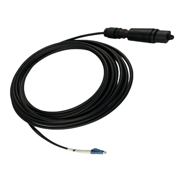
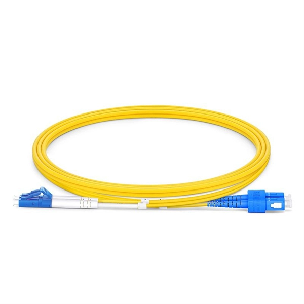
How to connect the connectors of optical fiber communication cables
In this guide, we'll walk you through the entire process of preparing fiber optic cable for splicing and termination to fiber connectors. We'll explore the necessary tools, safety precautions, and step-by-step procedures for cable connectors, mechanical and fusion splicing. Proper connection of fiber optic cables is essential to harness these benefits fully, as even minor errors can lead to significant performance issues like signal loss. Here's a step-by-step guide on how to connect fiber optic cables using fiber optic connectors and fusion splicing, which are the two main methods: Fiber optic connectors are used to quickly connect. There are many types of fiber optic connectors, including SC, LC, FC, ST, D4, MU, MT/MPO, etc. These connectors can be divided into single-mode and multi-mode fiber optic connectors according to their structure and purpose. 25mm ferrule, making them ideal for high-density applications. Understanding how to properly.
[PDF Version]
-
Method for Splicing Ribbon Optical Cables with Opening a Skylight
This guide walks you through the optimal process for splicing OptiRibbon cables to ensure flawless results every time. Splicing fiber optic cables may seem like a technical task, but it's an essential process for ensuring smooth, high-quality connections in any fiber network. Look at the slide graphics and then read the notes below. If you have your own equipment, do the recommended exercises. See the FOA Virtual Hands-On for the process of fiber optic. Ribbon cable can be spliced more rapidly by using mass fusion splicing technique. This is. Don't Miss this Super-Detailed Tutorial on Fiber Splicing and Winding! Don't Miss this Super-Detailed Tutorial on Fiber Splicing and Winding! The operation and skills of fiber optic fusion splicing technology can be mainly divided into five steps: fiber stripping, fiber cutting, fiber melting. Fiber optic splicing is the art and science of joining two separate optical fibers to create a continuous light path. Of course, this ribbon structure also allows for faster and less.
[PDF Version]
-
Buried optical cables lack markings
Public utility marks aren't enough. Free services like 811 only mark public utilities, not private lines like septic systems or private fiber optic cables. They don't carry electricity, so special tools like ground-penetrating radar (GPR) are. It is often necessary to locate buried optical fiber cable to prevent dig-ups during construction, to access fibers for termination, to effect repairs, or for other reasons. These include, but are not limited to:. Fiber optic cables are critical components of modern communication infrastructure, often buried underground for protection and durability. However, locating these cables can be challenging without the right tools and knowledge. Designed specifically for use in underground applications, our PVC marking flags are the perfect solution for. Cable and pipe locator tools are nondestructive evaluation (NDE) technologies that detect and identify buried cables and pipes based on the measurement of electromagnetic (EM) signals emitted by them. With international fiber networks predicted to grow to over 1.
[PDF Version]
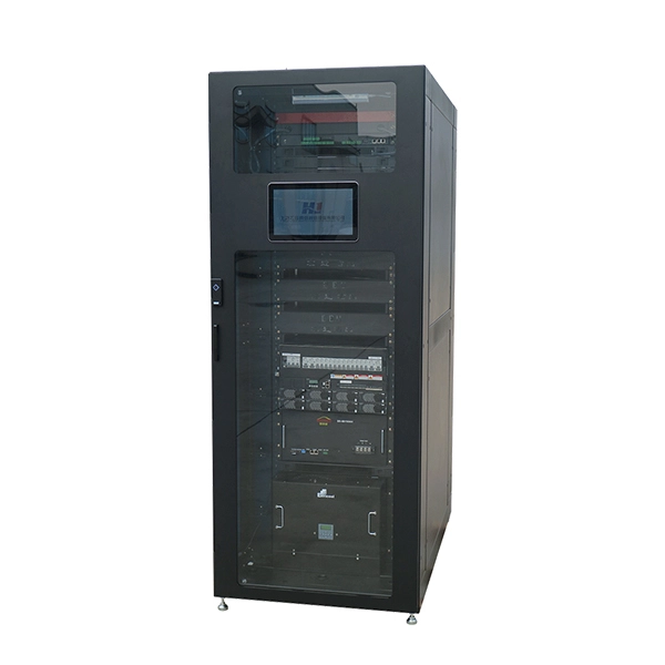
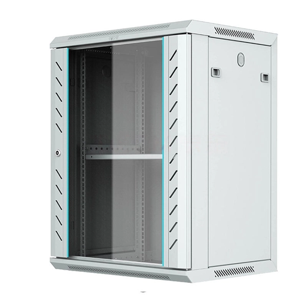
Telecom Racks & Cabinets
19-inch racks, wall-mount cabinets, open frames with high load capacity and seismic rating.
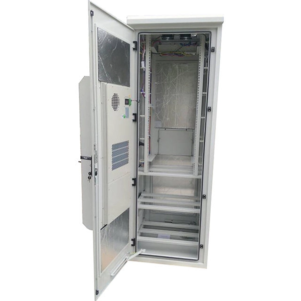
Outdoor Climate Cabinets
IP55/IP66 outdoor enclosures with integrated cooling/heating, -40°C to +55°C operation.
Smart PDUs & Power Distribution
Intelligent PDUs with remote monitoring, per-outlet switching, and environmental sensors.
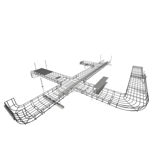
Shelters & Network Cabinets
Prefabricated telecom shelters, emergency comms shelters, and network cabinets with cable management.