-
What to do if the fiber optic cable splice loss is too high
If high loss persists, inspect the splicer's alignment system. Clean the V-grooves and objective lenses with appropriate cleaning sticks and isopropyl alcohol. Dirt or dust on the fibre ends is one of the most common causes of high splice loss. Fusion splicers have settings that must be tailored to your fibre type and condition. Modern fiber optic networks usually keep splice loss low, as shown below: You should know that each splice can add 0. Understanding its causes and solutions is critical for reliable fiber optic installations. Poor Fiber Cleave: Angled or chipped cleaves prevent proper. Neglecting minor problems can lead to higher splice losses, increased signal attenuation, and long-term damage to fibre networks. This. One problem I continue to see is unexpected high loss during spicing between exchange-to-exchange network, particularly in the feeder and backbone segments, which can seriously impact the performance of the PON networks.
[PDF Version]
-
Standard for 12-core optical cable splice loss
Splice-on connectors using fusion splices or mechanical splices which include a splice loss in the connector loss should be less than 0. Splices are critical points in the optical fibre network, as they strongly affect not only the quality of the links, but also their lifetime. High quality in splicing is usually defined as low splice loss and. The Contractor tasked to perform testing or splicing on any fiber optic cable will follow these testing standards to fulfill their contractual obligations. The Contractor must utilize the correct equipment and testing techniques to gain acceptance, or the work cannot be approved. A full catalog of TIA specs is at.
[PDF Version]
-
Multimode fiber optic splice loss standard
For multimode fiber, the loss is about 3 dB per km for 850 nm sources, 1 dB per km for 1300 nm. 5 dB/km max per EIA/TIA 568) This roughly translates into a loss of 0. Splicing is required to create a continuous path for light transmission from one fiber to another. Two different methods exist for splicing fibers: Typical splice loss values (the measure of loss in optical power across the splice point) are usually lower for fusion splices (typically less than 0. 1. To be able to judge whether a fiber optic cable plant is good, one does a insertion loss test with a light source and power meter and compares that to an estimate of what is a reasonable loss for that cable plant. The estimate, called a "loss budget" is calculated using typical component losses for. Acceptable dB loss for fiber depends on the component you're measuring: a single mated connector pair should lose no more than 0. 75 dB, a fusion splice should stay under 0. 5 dB per kilometer depending on the type and wavelength. The Contractor must utilize the correct equipment and testing techniques to gain acceptance, or the work cannot be approved. Optical fiber splicing is a critical.
[PDF Version]
-
How much loss does a fiber optic cold splice achieve
Acceptable splice loss in optical fiber is typically considered to be less than 0. Add connector counts, plus any splitter or fixed losses. Optionally add TX power and RX sensitivity to get PASS/FAIL. Click Calculate, then export CSV or PDF if needed. In single-mode fibers, light travels as a Gaussian beam. This tool uses the Marcuse Gaussian Approximation to calculate losses from intrinsic mismatch and extrinsic alignment errors. 5 dB per kilometer depending on the type and wavelength.
[PDF Version]
-
How to reduce optical loss in optical cables
Attenuation makes signals weaker in fiber optic cables. Check your optical transceiver's specs often. Scattering losses result from microscopic variations in the fiber's material density, compositional fluctuations, structural inhomogeneities, and manufacturing defects. Reducing these losses requires. Fiber optic cable, which is lighter, smaller, and more flexible than copper, can transmit signals with faster speed over longer distances. This technology supports the high-speed data demands of the modern world, from global internet backbones to local network infrastructure. As modern networks demand higher bandwidth and reliability, understanding optical fiber loss mechanisms and implementing strategies for automatic power reduction has become critical. Clean connectors before you use.
[PDF Version]
-
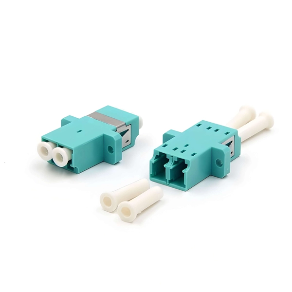
Sudan optical splitter miniature plug-in low loss vs wireless
This paper aims to study the design, simulation, and optimization of low-loss Y-branch passive optical splitters up to 64 output ports for telecommunication applications. For a waveguide channel profile, the standard material silica-on-silicon is used. Testing a splitter or other passive fiber optic devices like switches is little different from testing a patchcord or cable plant using the two industry standard tests, OFSTP-14 for double-ended loss (connectors on both ends) or FOTP-171 for single-ended testing. Splitters are essential when you want one fiber line from a central office (like an ISP's headend or data center) to serve multiple homes or businesses. These splitters feature a rugged miniature housing to fit into compact spaces in equipment and systems. It can distribute the optical energy transmitted through a single fiber to two or more fibers in a predetermined ratio or combine the optical energy from multiple fibers into one fiber.
[PDF Version]
-
Optical Amplifier Return Loss
Optical Return loss is defined as the ratio of incident to reflected power, expressed in decibels. This equation shows that a smaller reflection means a larger value of optical return loss. The term ORL is used to describe the ratio of relative magnitude of the cumulated back reflectance or multiple Fresnel events and backscattered signal power to the optical. Reflectance (which has also been called "back reflection" or optical return loss) of a connection is the amount of light that is reflected back up the fiber toward the source by light reflections off the interface of the polished end surface of the mated connectors and air. In high-speed single-mode links, DWDM systems, and even certain high-power laser applications, reflection. This AE Note explains the differences between Optical Return Loss (ORL) and Back Reflectance in fiber optic systems. The driving force behind understanding these topics is the ever-increasing high-speed transmission systems and the use of DWDM in the industry today. This topic is becoming critical. Beginning with software release 1.
[PDF Version]
-
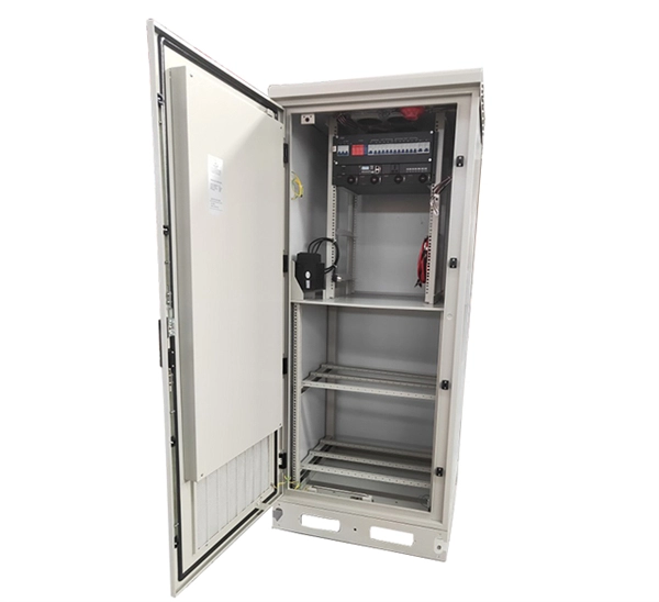
Sri Lanka earthquake-resistant server racks with low loss
100% designed and manufactured in Sri Lanka, under very tight tolerances. The heavy duty frame for Server applications will allow loading in excess of 2000kg without deformation*. The low profile design reduces internal non usable volume allowing air flow travel from front to back without creating. East Link Engineering Co. (Pvt) Ltd commenced operations in Sri Lanka on 15th September 1999 as Your One Stop LAN Product Supplier, and now it has expanded into group of companies, including the biggest manufacturing facilities, which focus on 19" Racks and Cable management products. Have any. Data Center Network Racks, manufactured and sold in Sri Lanka by Cubicoan Pvt Ltd, are available in an extensive range and are designed to meet modern standards, giving you peace of mind securing your equipment, whether it'll be for a data center or CCTV installation. The EIA-310 compliant mounting. Future Corporation (Pvt) Ltd has been incorporated as a limited liability company in Sri Lanka since 2007. Our head office and showroom are located at No. Sub distribution panels, Cable management systems and server rack systems for industrial and domestic applications in Sri Lanka.
[PDF Version]
-
Packet loss occurs when the device is connected to the switch
Packet loss can occur if any link in the chain has issues: Local Devices (e., PC, network card): Driver anomalies, aging network cards, or resource exhaustion. Access Layer (switches): Port congestion, broadcast storms, or loops. The first thing to do when troubleshooting it is to isolate where the loss is occurring. On a PC: To confirm if packet loss is occurring: This will ping the address. If you are experiencing packet loss or slow network performance on your local area network (LAN), you may need to troubleshoot your LAN switch. A LAN switch is a device that connects multiple devices on a network and forwards data packets based on their destination addresses. Imagine ordering a desk that ships in five boxes. Boxes 1, 2, 4, and 5 arrive undamaged, but box 3—containing every last screw, bolt, and connector, of course—has gone missing in logistics-land. But I have 2 hypotheses: The CAT5e cable between switch and modem cannot handle the traffic of 6 routers/apartments. This can result in various issues, including reduced network efficiency, application failures, and degraded quality of service for real-time applications such as VoIP and video.
[PDF Version]
-
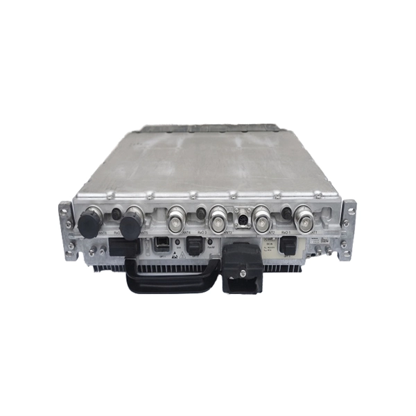
Long-distance optical transceivers with low loss 2026 model CE certified
Explore the critical role of telecom grade C-band transceivers in long-distance optical transmission, with specs, deployment insights, and expert guidance. Compared with 850nm or 1310nm SFP modules, 1550nm SFPs are designed for scenarios where signal attenuation, link budget. In the modern network, transceivers are categorized primarily by their reach (distance) and media type (Multimode vs. Miscalculating these distances leads to bit errors and link failures that can cripple a mission-critical environment. Hyperscale Data Centers: High-density spine-leaf. In the rapidly evolving landscape of hyperscale data centers, 5G Open-RAN architectures, and enterprise campus backbones, the optical transceiver has graduated from a commodity component to a critical strategic asset. From short-reach SR4 (hundreds of meters) to intermediate-reach LR4 (up to 10 kilometers), and further to. The Innoptical's IN-C2DCO-200G-LH coherent module, utilizes a trio of indium phosphide (InP) based PICs, covering the laser, modulation, and receiver functions. Through integration, we have enabled almost complete on-wafer test of our PICs. We have a FAE team to provide tailor-made network.
[PDF Version]
-
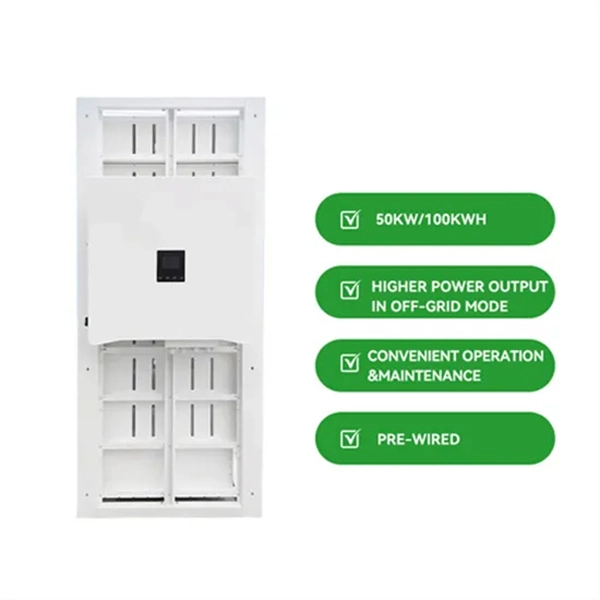
AC to DC power supply cold aisle low loss manufacturers
IQS Directory provides a comprehensive list of ac to dc converter manufacturers and suppliers. Low noise, efficient, reliable and easy to integrate power supplies are essential in medical device, semiconductor fabrication and industrial technology applications. Our broad range of cost-effective AC-DC power solutions includes flexible, configurable and custom products ranging from 3W to 3kW. Pico offers a comprehensive range of DC-DC converters with ultra-miniature, high-reliability designs featuring output voltages up to 10kV, output power up to 300 Watts, input voltage ranges up to 1200V and operating temperatures as wide as -55°C to +85°C for critical applications in aerospace. Cincon offers a range of robust, low-profile AC/DC power supplies tailored for various applications, all with a height of 1 inch. These supplies span power outputs from 200W to 750W and are available in semi-potted chassis type. With our newest addition, the LFM series, we provide both industrial. Daitron's state-of-the-art ultra low-noise power supply is ideal for systems that require low-noise environments.
[PDF Version]
-
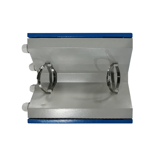
Loss of fused tapered beam splitter
They are constructed by fusing and tapering two fibers together. Typical excess losses are as low as 0. 2dB, while splitting ratios are accurate to within ±5 percent at the design. Fused couplers are used to split optical signals between two fibers, or to combine optical signals from two fibers into one fiber. Calculating Allowable Splitter Loss Application Note Introduction An optical signal degrades as it propagates through a network. The splitting ratio is defined as the ratio of the output power of each output port of a fibre splitter. The form birefringence which corresponds to the difference in the coupling coefficients between orthogonal polarization states causes the polarization splitting in the cou-pler. Understanding the types of splitters, their impact on network performance, and how to measure their losses ensures high-quality network operation and facilitates optimal splitter selection based on.
[PDF Version]
-
1 to 32 splitter insertion loss
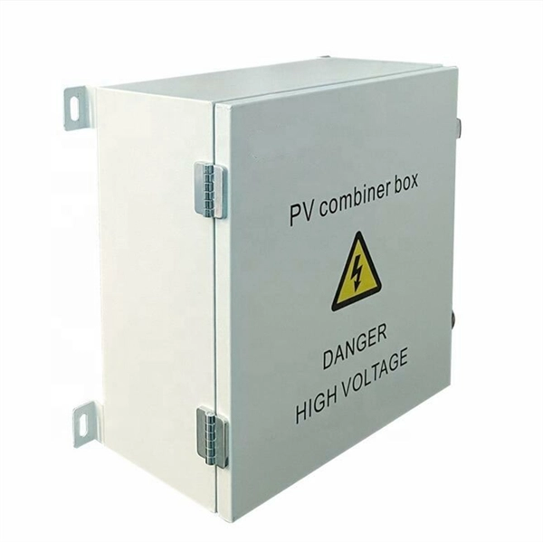
A 1:32 splitter divides input power by ~32 (adding ~15dB of insertion loss), so the remaining power supports signals up to 20km. Calculate insertion loss for passive optical splitters in PON and distribution networks. Power is divided equally among output ports. This is a single-direction budget estimate; downstream and upstream wavelengths or optical classes may. Optical insertion loss refers to the signal loss resulting from the insertion of components such as connectors or splices in an optical fiber system. Common values: 2, 4, 8, 16, 32, 64.
[PDF Version]
-
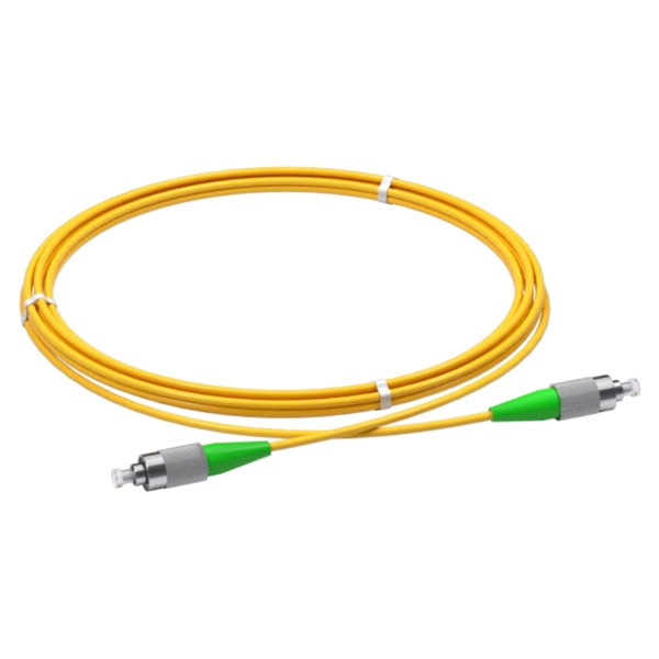
Packet loss in 10 Gigabit single-fiber optical module
For singlemode fiber, the loss is about 0. 5 dB per km for 1310 nm sources, 0. 1 dB per 600 (200m) feet for 1310. Key factors to consider in the design of 10 Gigabit Ethernet networks are: The network topology, including operating distances, splice losses and numbers of connectors (i. These modules offer low signal loss and minimal distortion, making them ideal for applications in metropolitan area networks and campus settings. Choosing the right fiber. The Cisco ® 10GBASE SFP+ modules (Figure 1) give you a wide variety of 10 Gigabit Ethernet connectivity options for data center, enterprise wiring closet, and service provider transport applications. When dealing with single mode fiber (SMF) in optical communication systems, understanding and managing the acceptable dB (decibel) loss is crucial for maintaining efficient and reliable signal transmission. They are compliant with SFF-8431, SFF-8432 and IEEE 802. 3ae 10GBASE-LR/LW, and 10G Fibre Channel 1200-SM-LL-L Digital diagnostics functions are available via a 2-wire serial interface. The transceiver is a “limiting module”, i. This article aims to explore this issue. 1 Attenuation Characteristics.
[PDF Version]
Telecom Racks & Cabinets
19-inch racks, wall-mount cabinets, open frames with high load capacity and seismic rating.
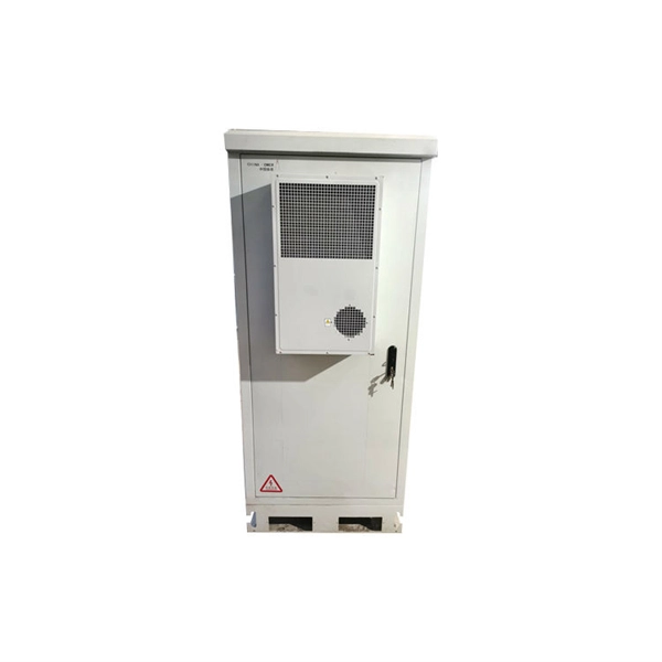
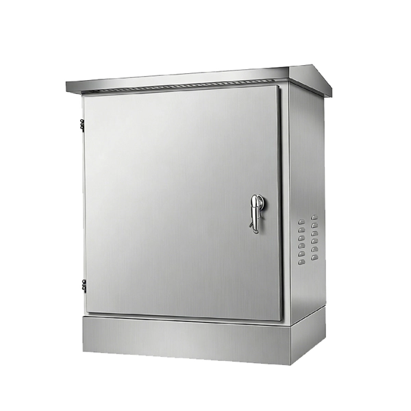
Outdoor Climate Cabinets
IP55/IP66 outdoor enclosures with integrated cooling/heating, -40°C to +55°C operation.
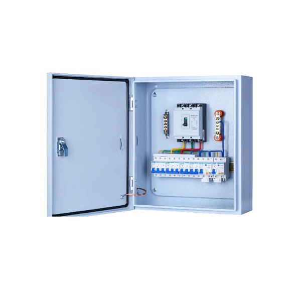
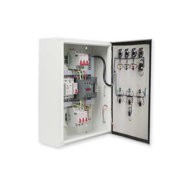
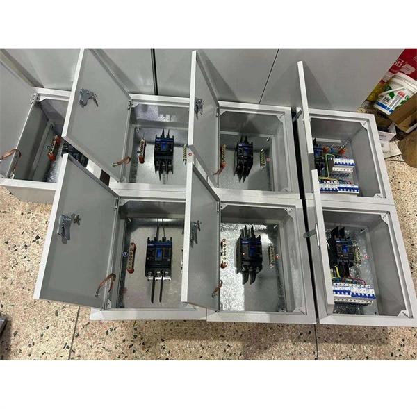
Smart PDUs & Power Distribution
Intelligent PDUs with remote monitoring, per-outlet switching, and environmental sensors.
Shelters & Network Cabinets
Prefabricated telecom shelters, emergency comms shelters, and network cabinets with cable management.