-
Calculation of distance from cable tray bend to wall
Calculate horizontal, vertical, or compound cable tray offsets based on bend angle, offset distance, and available installation space. Measure this distance along the straight tray. Two Bends Per Offset: Every offset requires two equal bends — one to move laterally and one to return to parallel. The total tray section consumed = 2 × single bend length. Pre-fab vs Field Bent: For standard offsets (6, 12, 18 in at 45°), use manufacturer pre-fabricated offset fittings to save. When installing two cable trays in parallel at the same height, the distance between them should be no less than 0. This spacing is crucial for adequate maintenance access, ease of inspection, and ensuring proper airflow for effective heat dissipation. ) that matches or exceeds this value. 8 (Other Mechanical Stresses (AJ)) in that document provides requirements for cable support. IEC 61537 covers cable tray and cable ladder systems for the support and accommodation of cables, while NEC Article 392 governs cable.
[PDF Version]
-

Fabrication and Installation of Cable Tray Supports in Factory Buildings
This guide covers the critical steps, from selecting the right electrical cable tray and performing accurate cable fill calculations to managing a safe cable pull through and ensuring all bonding and grounding requirements are met. Cable tray systems provide a safe, organized, and flexible method for supporting insulated conductors and cables in commercial and industrial electrical installations. When properly selected and installed, cable trays simplify routing, improve accessibility, and support future expansion while. Cable management in buildings and industrial premises is a very important aspect. These guidelines are not intended to cover all details or variations in cable ladder and cable tray. in this document have been tested extens ompetent professional en completely installed, without damage either to conductors or structural system use maintain spacing or to keep cables in place when the tray is ect the minimum bend ra-dius for cables as they exit the bottom of the cable tray. Using the example and guide below, create your.
[PDF Version]
-
What to do if a cable tray bend is sagging
Ensure proper tray sizing: Avoid overloading or under-loading trays. Test and inspect: Perform thorough testing and inspection before commissioning. Regularly inspect: Check for signs of damage . When a load is more than the structural capacity of a cable tray, it bends between supports. Safety questions and cable damage can follow from this. Here are main approaches to either fix or stop drooping: 1. Insufficient Cable Support and Sagging Cable sag results from incorrect spacing of cable tray supports or from employing the incorrect tray type that is, light-duty perforated trays in high-load applications. They come in various forms, including ladder trays, solid-bottom trays and wire mesh trays such as stainless steel wire cable trays. Usually we provided support to cable tray every 3 m, If. Addressing cable tray failures requires a combination of regular maintenance, timely repairs, and preventive measures.
[PDF Version]
-
Calculation formula for cable tray supports and hangers
Cable tray support quantity can be calculated using a simple formula: Support Quantity = Total Length ÷ Support Spacing + 1 20 ÷ 2 + 1 = 11 supports In a typical project, a 20-meter cable tray with 2-meter spacing requires 11 supports. As a key structure supporting the cable tray, the accurate calculation of the support quantity directly affects construction costs, efficiency, and safety. Follow these simple steps: Define Tray Dimensions: Enter the width and depth of your planned cable tray (in mm or inches). Select Fill Standard: Choose 40% for power cables (NEC compliant) or 50% for. The formula to calculate the cable tray capacity is: [ CTC = text {floor}left (frac {W cdot H cdot FR} {CA}right) ] Where: ( CTC ) is the cable tray capacity (number of cables). This article details everything from permitted uses and cable types to fill capacities and. Table 1: IEC Common Ladder and Tray Dimensions Note: Quantities above are approximate and assume single-layer horizontal mounting without fill derating. The International Electrotechnical Commission (IEC).
[PDF Version]
-
Calculation formula for cable tray supports in factory buildings
Cable tray support quantity can be calculated using a simple formula: Support Quantity = Total Length ÷ Support Spacing + 1 20 ÷ 2 + 1 = 11 supports In a typical project, a 20-meter cable tray with 2-meter spacing requires 11 supports. As a key structure supporting the cable tray, the accurate calculation of the support quantity directly affects construction costs, efficiency, and safety. In complex engineering environments, the. Stop Costly Cable Tray Installation Errors Now: Avoiding Mistakes in Instrumentation Cable Tray Installation: A Guide for EPC Projects Cable tray sizing in real EPC projects is not limited to simple area calculation. Formula 1: Cable Tray Fill Ratio Where: Total Cable Area (mm²) = Sum of.
[PDF Version]
-
How many degrees should the cable tray bend be
According to the NEC, the total bend in a continuous run is limited to 360 degrees. “There shall not be more than the equivalent of four quarter bends (360 degrees total) between pull points, for example, conduit bodies and boxes. ” What Happens if the Wire Bends Too Much?How to calculate cable tray bends? Calculate the minimum required bend radius by multiplying the cable's outside diameter by its bending factor (e. Then, select a standard tray fitting (300mm, 450mm, etc. ) that matches or exceeds this value. The length of the bottom side (bottom diagonal) after bending the cable tray should be equal to the width of the cable. In a typical installation, if a cable measures 10 mm across and requires a 6× bend, the bending radius should not be less than 60 mm. You just need to remember the “multiplier for the outer diameter”, and it will be much easier to install the cable. 5"L; Black; Cable Capacity - 947 Category: 90° Vertical Outside Tray Bend 90° Radius Juncture, 2 inch Depth x 12 Inch Width, Pre-Galvanized Steel.
[PDF Version]
-
How to bend cable trays over beams
You can buy a manufactured 90 degree bend or make one on a cable tray bending machine but in this video I show you how to make one using a metal bar. Students trading aid on how best to put an internal 90 degrees bend in steel cable tray. By following these steps, you can minimize the risk of damage to the cable tray and ensure a smooth bending experience. When a wire cable tray is cut, the fact that a. This publication is intended as a practical guide for the proper and safe* installation of cable ladder systems, cable tray systems, channel support systems and associated supports. Cable ladder systems and cable tray systems shall be manufactured in accordance with BS EN 61537, channel support. The screw-on cable trays are available in perforated (MKS, SKS, DKS, EKS, IKS) and unperforated (MKSU, SKSU, EKSU) versions. The sys-tems include numerous connectors, fittings – such as bends, add-on tees, T and reducers, cross-overs and covers – and further accessories.
[PDF Version]
-
Cable tray flame retardant report
This memorandum transmits the results of a completed portion of the NRC Fire Protection Research program relating to the effectiveness of cable tray fire retardant coating materials and barriers in retarding the combustion within and propagation between horizontal cable trays. ucts; however, as an alternative DIN 4102-12 can be used. This is a test for electric cable systems that are required to maintain circuit integrity, so is therefore written around and is dependent on the cables themselves, but containmen of 90 minutes (the maximum time covered by DIN 4102-12). EAE Group of Companies started its journey in the electrical sector in 1973 with the establishment of EAE Elektrik. Since its founding, EAE has grown rapidly, expanding its production and areas of operation by incorporating EAE Lighting in 1983, EAE Machinery in 1996, EAE Electrotechnics in 2004. Vertical-tray flame tests are commonly used in the wire and cable industry to analyze cable flame propagation for industrial control and power cables. This guide walks you through everything—testing standards, methods, equipment, and what the results mean for.
[PDF Version]
-
Fireproof putty at the end of the cable tray
Choose appropriate fire protection materials, such as fire-rated board, firestop packs, firestop mastic, or fire-resistant mineral wool. Firestop packs should be placed in an orderly sequence. The following charts give the number of 3M pillows needed to completely firestop an opening that cable tray passes through. UL Listed Systems Concrete Wall - C-AJ-4056 3 HR F-Rating, 3/4 HR T-Rating Gypsum. Putty provides draft and cold smoke seal Pliable and conformable design easily molds into required shapes For industrial/occupational use only. 3M™ Fire Barrier Moldable Putty Stix MP+ is a one-part, re-enterable, intumescent putty that can be easily formed to firestop. This document outlines the 3M Fire Barrier product line, designed to provide effective firestopping solutions for cable tray systems and various through-penetrations. Prices vary for Hawaii, Alaska and US Territories. For approval or certificate information, please see individual items. Ensure you have the right solution for your.
[PDF Version]
-
Ranking of Jordanian Cable Tray Brands
Explore top Cable Tray Manufacturers in the Middle East for reliable, compliant solutions in oil, gas, construction, and more. Based in Ajman, UAE, Emerald Steel Industries is a prominent manufacturer of cable trays, cable ladders, and cable management systems. With a strong presence in the Gulf region, they are recognized for their ability to deliver high-quality products tailored to meet the demands of the Middle East's. Brilltech Engineers Pvt. This Local Businesses in, Jordan are verified through email. Which is the best Cable Trays & Ladders in. MASEICO cable trays system has been designed and developed according to the latest international standards and measures in order to maintain the best installation solutions. Every buyer chooses us first because of our excellent finishing and high-quality. Masoudia Electrical Industries Co.
[PDF Version]
-
Does cable tray layout with layered cables count
For cables larger than 4/0 AWG, cables are installed in a single layer (no stacking) and the sum of cable diameters must not exceed the tray width. NEC Article 392 governs cable tray installations, covering tray types, fill limits, cable types permitted, and ampacity adjustments. The fill rules differ significantly between single-conductor cables and multiconductor cables, and between ladder tray and solid-bottom tray. 80 (A) (1) (c) for single-layer maintained-spacing conditions). Be sure to use the specific subsections in 392. A rung spacing of 6 to 9 inches (150 to 230 mm) is preferable when the cable tray cont d for instrumentation and control applications that require. NEC Article 392 outlines the key rules for installing and maintaining industrial cable tray systems. The content is written to be SEO-friendly and compatible with Yoast SEO for WordPress.
[PDF Version]
-
Ladder-type cable tray parameters and principles
The Ladder Tray features light, rugged, tubular steel construction. It is designed for mechanical support and strain relief in long runs of cable and creates a smooth gradual bend for cable. The cable tray system shall conform to the material and fabrication requirements as per this specification. Standard for Non-Metallic Cable Tray Systems 2. Eaton's submittal builder tool. us-trations without notice. The mechanical and electrical characteristics, tests, certifications, overall quality management, recommendations mentioned. rays are to be constructed of AiSA type 304 or 316 s All trays to be l be a of the cable e tray side-rails and wrap around and snap onto each section of tray.
[PDF Version]
-
Belgian New Materials Cable Tray Company
Trayco is specialised in producing and optimising 100% Belgian cable trays, mesh trays, cable ladders, mounting and floor systems. We also play an important role as advisor and guide during the installation process. Strong in production, optimisation and consulting for cable support systems Trayco's solar shelter kits: assemble your PV inverters at lightning speed! Discover the new Trayco catalogue! Request your new product catalogue and dive into our extensive range of cable support systems! Get more info on. Niedax Belgium was founded in 2005 as a subsidiary company of the Niedax Group, with its head office located in Germany. Today, the company can offer a very wide range of more than 50,000. For 40 years, we have been providing reels, garlands, multiple. We jointly push you to a faster installation ! Belgian manufacturer, with trade sales and expert advice of cable support systems.
[PDF Version]
-
Angola Cable Tray Laying Scheme
This document outlines the key requirements for cable tray layout, installation, and fireproofing in industrial and commercial environments. Route Planning and Layout PrinciplesAt Angola Wire, we specialize in providing a diverse range of building cable trays, available in various materials and finishes. This process is integral to determining the optimal arrangement and configuration of cable trays, which are essential for routing and supporting electrical cables within buildings and. Cable tray installation must comply with specific technical standards to ensure electrical safety, system reliability, and long-term maintainability. Adherence to these guidelines is essential: 1. Moreover, our focus on maintaining high quality and.
[PDF Version]
-
New Zealand Stainless Steel Cable Tray Specifications
Manufactured from Grade 304 Stainless Steel or Grade 316 on request. Our standard widths are 60mm,100mm,150mm,200mm,300mm,400mm,450mm,500mm & 600mm. In the smaller sizes (60mm-100mm) we can also fabricate trays with 30mm side walls. SEP Manufacturer all components and. ng; Power, Data, and Audio Visual. A quick and easy system to install without the need for specialised tools or equipment, makes it a first choice for Comm solution that works for your job. CM001034 Cable Mesh Tray | Stainless Steel 316 | ! Steel & Tube offer a full range of cable trays and cable ladders suitable for all cable containment, and additionally can provide full take-offs from plans through to a complete quotation. Click the Design details link for access to a large library of BIM-enabled 2D and 3D CAD roofing details. Runnur Solar Cable Tray Flat Cover 150mm x 3metre Zn-Mg-Al Alloy Coating Steel A robust and high corrosion resistance cable management system designed. Our mission is to deliver high performance products you can.
[PDF Version]
Telecom Racks & Cabinets
19-inch racks, wall-mount cabinets, open frames with high load capacity and seismic rating.
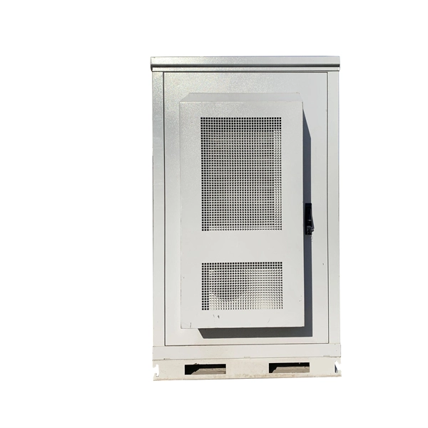
Outdoor Climate Cabinets
IP55/IP66 outdoor enclosures with integrated cooling/heating, -40°C to +55°C operation.
Smart PDUs & Power Distribution
Intelligent PDUs with remote monitoring, per-outlet switching, and environmental sensors.
Shelters & Network Cabinets
Prefabricated telecom shelters, emergency comms shelters, and network cabinets with cable management.