Michelson Interferometer Diagram and How It Works
The beam splitter divides the incoming light wave into two distinct beams, with roughly half the light being reflected and the other half transmitted. The two resulting beams travel along perpendicular
The Michelson Interferometer
Interferometry is a central building block for many optics measurements and a versatile tool in the laser lab. Here we describe the general working principle and give a systematic and simple setup and
Schematic of a beam splitter to illustrate the difference
Figure 3 shows a schematic of a simple experiment with a beam splitter that illustrates the separation fallacy, which is a common misconception.
Beam Splitter Input-Output Relations
The elements of the beam splitter transformation matrix B are determined using the assumption that the beamsplitter is lossless. While a beamsplitter is never lossless, it is a good approximation for most
Physics:Beam splitter
A beam splitter or beamsplitter is an optical device that splits a beam of light into a transmitted and a reflected beam. It is a crucial part of many optical experimental and measurement
Beam Splitter | Precision, Applications & Design Principles
Explore the precision, applications, and design principles of beam splitters, essential for advancements in scientific research and technology.
Interferometer_Lab
When a lens is placed between the laser source and beam-splitter, the light ray spreads out, and an interference pattern of dark and bright rings, or fringes, is seen on the viewing screen (see figure to
Beam splitter
A beam splitter or beamsplitter is an optical device that splits a beam of light into a transmitted and a reflected beam. It is a crucial part of many optical experimental and measurement systems, such as
1. Introduction 2. Michelson interferometer: theory
Light from a source unit N (a mercury or sodium lamp, in this experiment), passing through a diffusing screen/filter holder unit D, is incident on the plane-parallel beam splitter plate with compensating
The Michelson Interferometer
Light from the source strikes the beam splitter (designated by S). The beam splitter allows 50% of the radiation to be transmitted to the translatable mirror M1.
Michelson Interferometry
Figure 2 shows the schematic of the Michelson interferometer. The Michelson Interferometer is an amplitude-splitting interferometer. It splits the beam into two perpendicular paths using a 50 % beam
Telecom Racks & Cabinets
19-inch racks, wall-mount cabinets, open frames with high load capacity and seismic rating.
Outdoor Climate Cabinets
IP55/IP66 outdoor enclosures with integrated cooling/heating, -40°C to +55°C operation.
Smart PDUs & Power Distribution
Intelligent PDUs with remote monitoring, per-outlet switching, and environmental sensors.
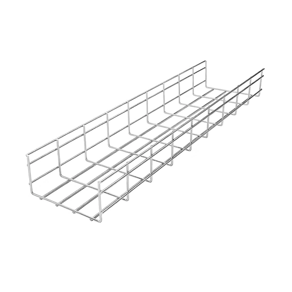
Shelters & Network Cabinets
Prefabricated telecom shelters, emergency comms shelters, and network cabinets with cable management.