Mass Fusion Splicing of Optical Fiber Ribbon Cables
Fusion splice is a junction of two or more optical fibers that have been melted together. This is accomplished with a machine called a fusion splicer that performs two basic functions: aligning of the
The FOA Reference For Fiber Optics
Look at the slide graphics and then read the notes below. The notes explain the process. If you have your own equipment, do the recommended exercises. See the FOA Virtual Hands-On for the process
Fusion splicing
The goal is to fuse the two fibers together in such a way that light passing through the fibers is not scattered or reflected back by the splice, and so that the splice
Arc Fusion Splicing of Photonic Crystal Fibres
Fusion splicing involves localized melting of two fibre butts pressed together, with fibre coating removed.
Experiment No. 16 Splicing of optical fibers
Fusion splicing is the most permanent and lowest loss method of connecting optic fibers. In essence, the two fibers are simply aligned then joined by electric-arc welding (The arc that occurs between the two
Fiber Optic Fusion Splicing Guide: From Safety to Troubleshooting
Learn Fiber Optic Fusion Splicing: step-by-step guide to safe, precise fiber prep, fusion, and testing for low-loss, high-quality splices in optic networks.
Fusion Splicing: Techniques and Tools | PDF | Optical Fiber
Fusion splicing is the process of fusing two optical fibers together using an electric arc to provide the lowest loss and strongest joint. It is the most common splicing method for single-mode fibers.
Fusion Splicing with Panduit Products
Background Splicing is a necessary field option, not only for repair, but also to enable customers to break ultra-high fiber count distribution cables down at demarcation points to route to other locations
The FOA Reference For Fiber Optics
When fusion is completed, the splicing machine will inspect the splice and estimate the optical loss of the splice. It will tell the operator if a splice needs to be remade.
How to Splice Fiber Optic Cable – Step-by-Step Fusion Splicing Guide
In this guide, you will find a chronological description of the fusion splicing process, the principal technical standards, and answers to the real-life questions network engineers and

Schematic diagram of single-mode fiber fusion-splicing, (a): optical
Breakage and damage of fiber optic cable fibers seriously affects the normal operation of fiber optic networks, and it is important to quickly and accurately determine the type and location...
4. Optics of Fusion Splicing
Schematic illustration of the effect of a fusion splice joint on an optical signal propagating from left (launching fiber) to right (receiving fiber).
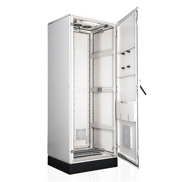
Telecom Racks & Cabinets
19-inch racks, wall-mount cabinets, open frames with high load capacity and seismic rating.
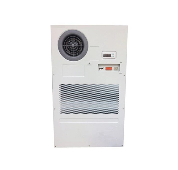
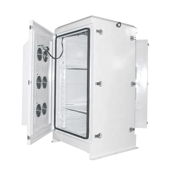
Outdoor Climate Cabinets
IP55/IP66 outdoor enclosures with integrated cooling/heating, -40°C to +55°C operation.
Smart PDUs & Power Distribution
Intelligent PDUs with remote monitoring, per-outlet switching, and environmental sensors.
Shelters & Network Cabinets
Prefabricated telecom shelters, emergency comms shelters, and network cabinets with cable management.