Plan, Install & Firestop Cable Penetrations
Tray openings (especially multiple tray openings) are usually a great deal larger than required to run the tray itself. The area within the tray is designed to carry the cables.
6H Wall Penetration Sleeve | Ladder Trays | Cable Tray and Reels
Fabricated cable tray wall sleeves from Legrand, provide safe, rigid and aesthetically pleasing support at a wall requiring cables to continue through the wall. Legrand wall sleeves, WPS, are an economical
Cable Tray Penetrations: Problem Solved!
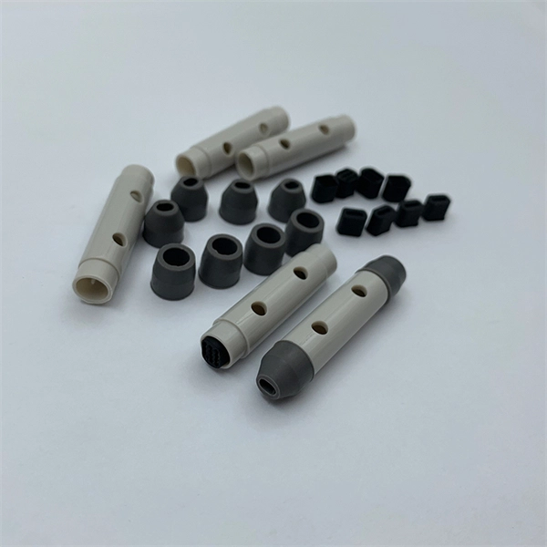
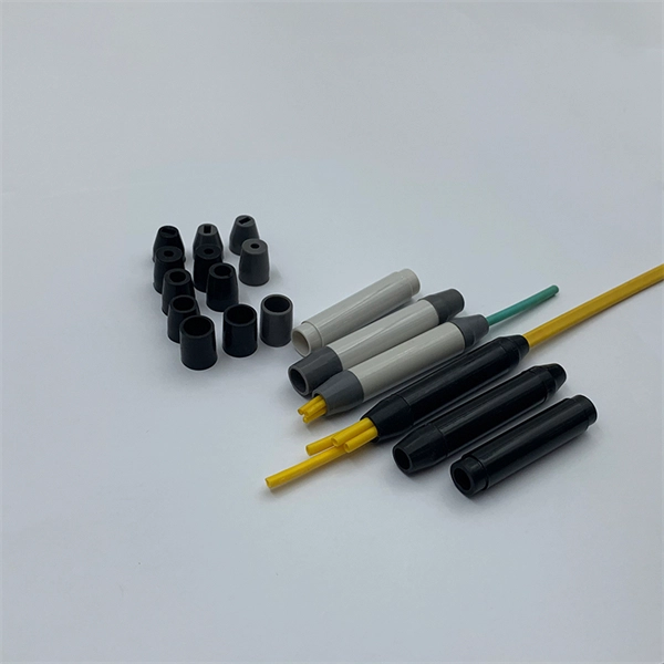
A series of small holes is always easier to deal with than one large hole. Cable trays requiring a ground can run a ground wire through a one-inch sleeve to isolate it from the communications cables.
Cable tray manual
Instead of large conduits, cable channel may be used very effectively to support cable drops from the cable tray run to the equipment or device being serviced and is ideal for cable tray runs involving a
Cable Tray Installation Rules (NEC 392) – Electrical Trader
NEC Cable Tray Fill Capacity Chart by Tray Width and Cable Type Properly calculating cable tray fill capacity is essential to avoid overheating, equipment damage, and code violations. You
Cable Tray Manual: NEC Article 392 Guide
Standard widths for ventilated trough cable tray systems are 6, 9, 12, 18, 24, 30, and 36 inches. The standard bottom configuration for ventilated trough cable tray is a corrugated bottom with 27/8 inch
Cable Tray Dimensions and Specifications as per NEC
The entire amount of the cross-sectional areas for all of the single conductor cables that are going to be positioned in the cable tray needs to be equal to or less than the permissible cable
A Guide to Installing and Supporting Electrical Cable Trays
This guide covers the critical steps, from selecting the right electrical cable tray and performing accurate cable fill calculations to managing a safe cable pull through and ensuring all bonding and grounding
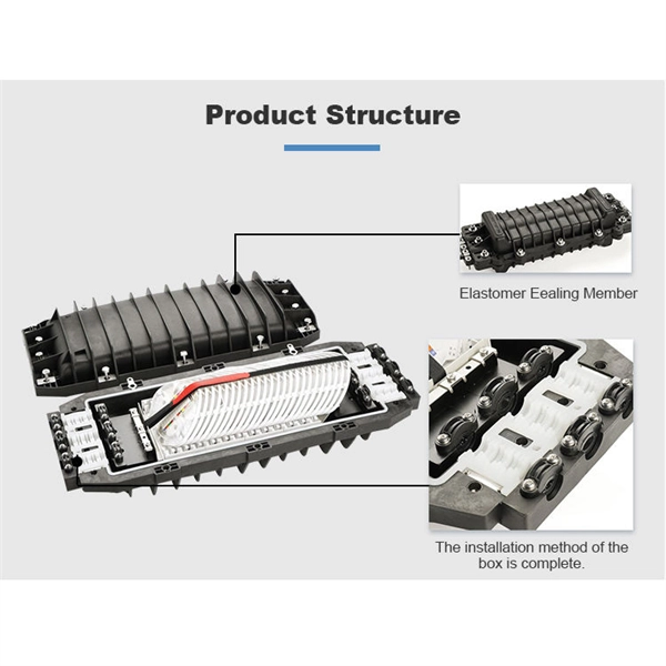
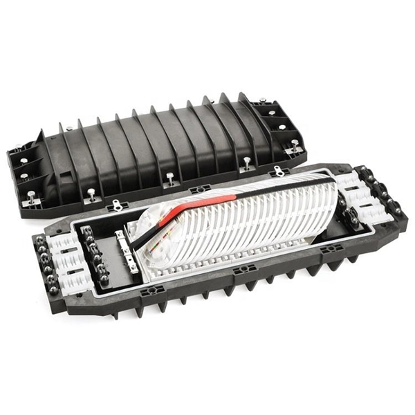
Cable Penetration Seals | ZAPP-ZIMMERMANN GmbH
Up to 6 in. by 24 in. steel or aluminum cable tray with max. 45% cable fill F-Rating: 2 h; T-Rating: 0 h Max. opening size: 384 in.² with a max. dimension of 32 in. Floor or wall of min. 4 ½ in. thick
I-BEAM Wall Penetration Sleeve
Welded aluminum I-beam ladder cable trays are a core solution and an iconic design in the cable tray industry. The I-beam design is the most common cable tray construction. Our aluminum, I-beam
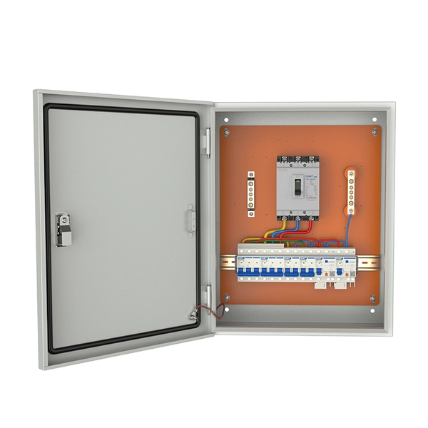
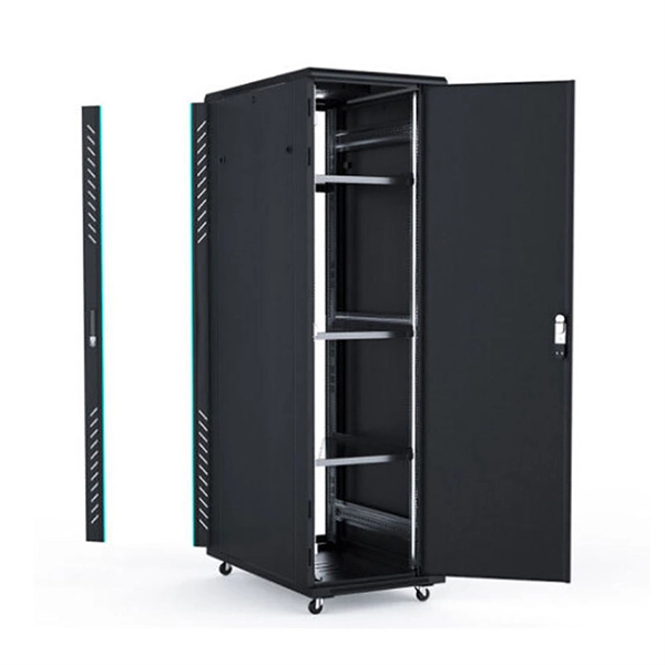
Telecom Racks & Cabinets
19-inch racks, wall-mount cabinets, open frames with high load capacity and seismic rating.
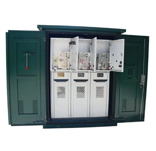
Outdoor Climate Cabinets
IP55/IP66 outdoor enclosures with integrated cooling/heating, -40°C to +55°C operation.
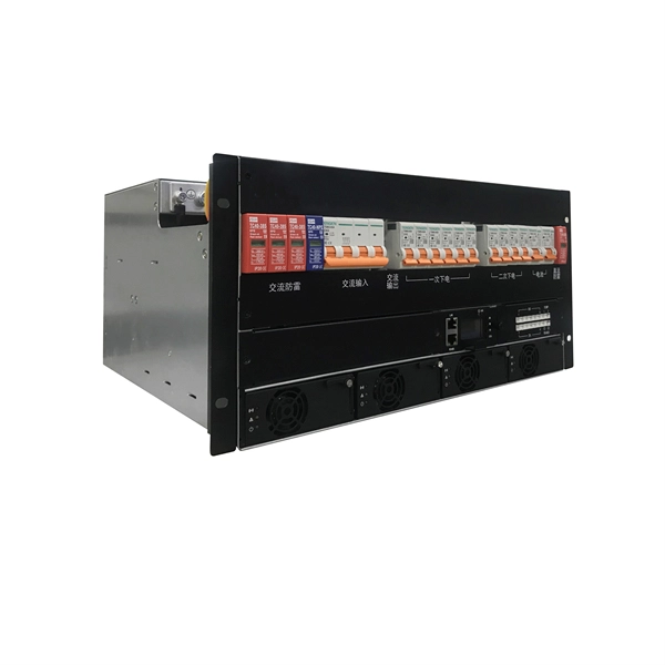
Smart PDUs & Power Distribution
Intelligent PDUs with remote monitoring, per-outlet switching, and environmental sensors.
Shelters & Network Cabinets
Prefabricated telecom shelters, emergency comms shelters, and network cabinets with cable management.