Method Statement installation of Cable Trays and Ladders
This method statement covers the site installation of the cable tray & ladders and the requirements of checks to be carried out.
Busway and Cable Tray Installation
It involves calculating angles and bends as well as measuring and cutting cable trays prior to overhead installation. Because this task requires work at elevation, ladders or other types of lift equipment are
GUIDE CABLE TRAYS TECHNICAL
When fitting cable trays and their accessories, the products are cut on site to create changes of direction, adjust sections, etc. Damage can also occur during handling; as a result, both the
Cooper B-Line
To properly evaluate a cable tray wiring system vs. a conduit wiring system, an engineer must be knowledgeable of both their installation and the system features. The advantages of cable tray
Cable Tray Design and Sizing Guide | PDF
The document discusses several key factors to consider when designing a cable tray system, including: 1) The width and height of the tray, type of tray bottom (ladder, ventilated, or solid), and type of

Elevation of cable trays
Generating the correct elevation of cable trays for the ortho drawings in Plant3D can be tricky. But a very simple solution is here!
SECTION 260536
Show fabrication and installation details of cable tray, including plans, elevations, and sections of components and attachments to other construction elements.
Best Practice Guide to Cable Ladder and Cable Tray Systems
The radius for cable ladder and cable tray fittings is usually determined by the bending radius and stiffness of the cables installed on the cable ladder or cable tray.
Document DICOS
To install the cable tray supports, first find the required elevation from the floor to the bottom of the cable tray and establish a level line with a laser or a nylon string.
B-Line series Cable Tray Design Considerations
For ladder or ventilated trough trays, the total sum of the cross-sectional areas of all the cables to be installed in the cable tray must be equal to or less than the allowable cable area for the tray width, as
SECTION 26 05 36 CABLE TRAYS FOR ELECTRICAL
Designer shall provide a 12” vertical working clearance above the cable tray with no continuous obstructions. In addition, a 12” space must be provided on either side for working access.
METHOD STATEMENT FOR CABLE TRAY INSTALLATION
2.0 This method statement will cover the minimum requirements for installation of cable trays and other related electrical works to be applied at the site for commercial buildings, plants and refineries.
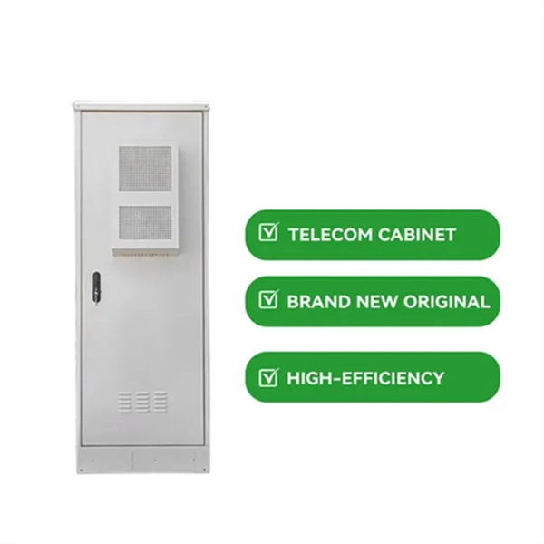
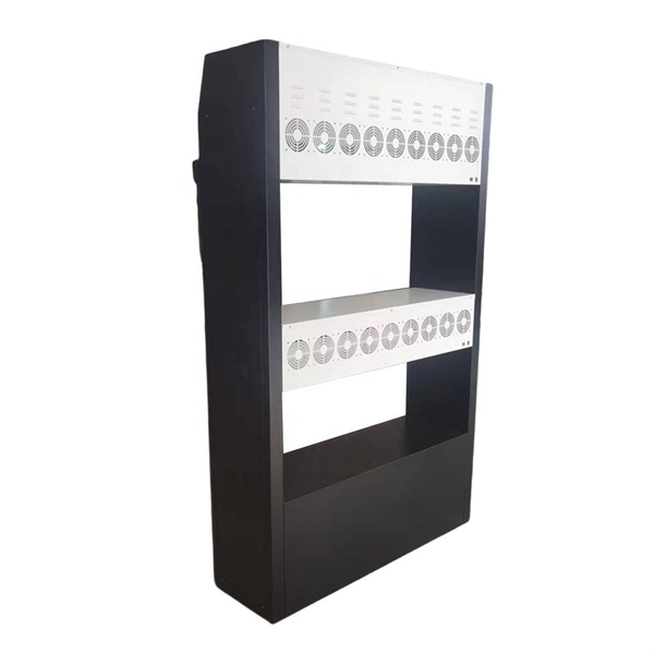
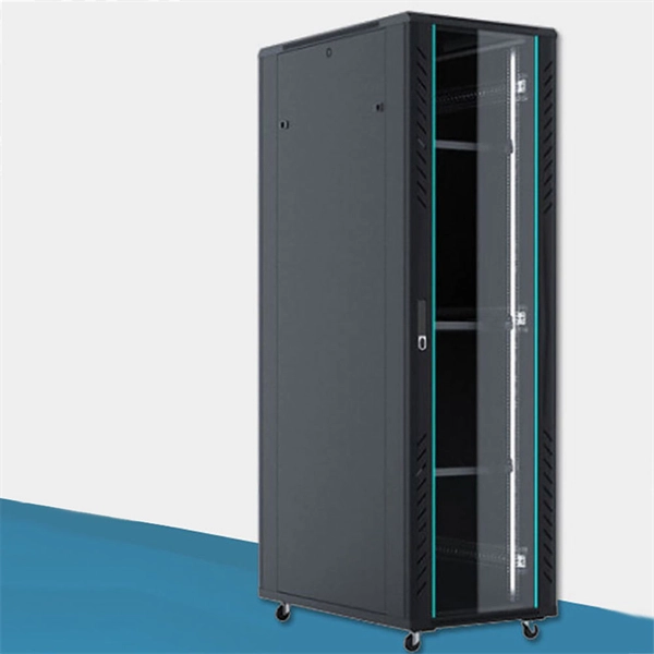
Telecom Racks & Cabinets
19-inch racks, wall-mount cabinets, open frames with high load capacity and seismic rating.
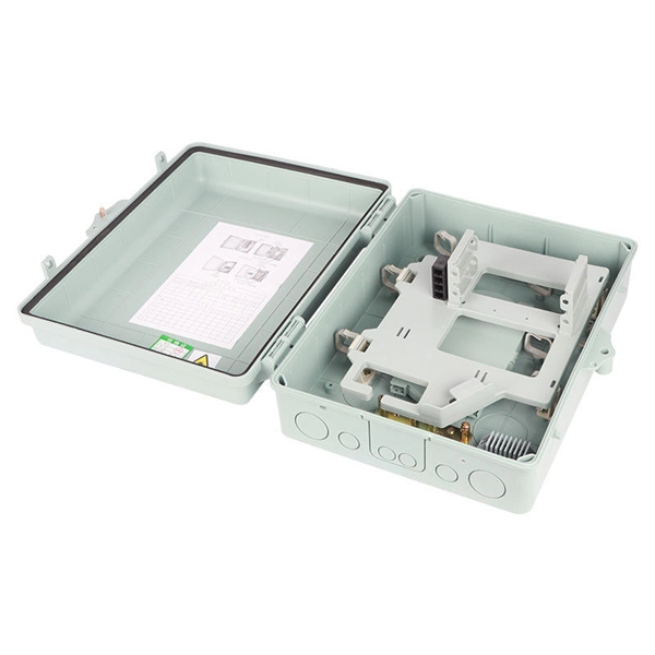
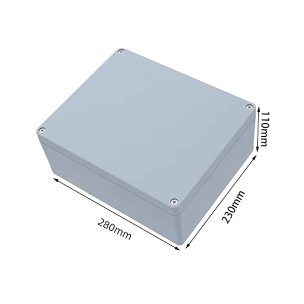
Outdoor Climate Cabinets
IP55/IP66 outdoor enclosures with integrated cooling/heating, -40°C to +55°C operation.
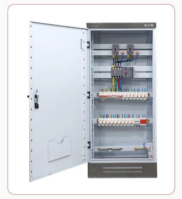
Smart PDUs & Power Distribution
Intelligent PDUs with remote monitoring, per-outlet switching, and environmental sensors.
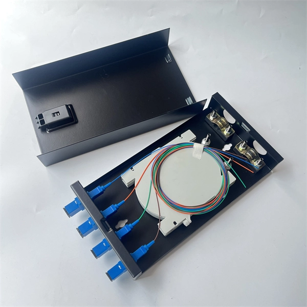
Shelters & Network Cabinets
Prefabricated telecom shelters, emergency comms shelters, and network cabinets with cable management.