
Railroad Interconnect Preemption Circuit
Railroad Interconnect Preemption Design Simultaneous preemption, Advance preemption, Gate down/island, Advance pedestrian preemption, and Traffic signal health status
Contrast
RAILROAD INTERCONNECT WIRING (TYPICAL) Use #12 AWG wire for either option Traffic Signal Cabinet
Bruce Chubb''s Computer/Model Railroad Interface (C/MRI) 101
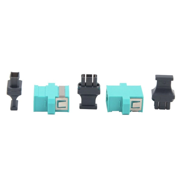
The boards use the standard network CAT5/6 cable (8 wires) to help with wiring. It has an RJ45 connecter for that cable on one end and either a Molex connector or a screw terminal block on the
2070 RR Preemption and Blankout Sign Control Box
Provides an output which directs the controller to begin the even when cabinet is in the flash mode. circuitry allows the blankout signs to operate normally, blankout signs required by the preemption

Systems Standard Drawings Rev 1
STANDARD DRAWINGS SHALL BE USED IN THE DESIGN OF INTERFACE POINTS, PROJECT SPECIFIC ITEMS OF WORK OR AS A BASIS FOR PRESENTATION OF DESIGN
Rail Infrastructure Manuals and Product Catalogs
Discover expert rail infrastructure solutions: comprehensive catalogs, videos, and guides for communication, crossings, and electromechanical systems.
SWARCO McCAIN RAILROAD INTERFACE PANEL
A health circuit, consisting of a mechanical relay, indicates to the railroad if an issue arises with the traffic cabinet, e.g. if there is a problem with the TCR and SUP field wires, which can cause the
WIRING
To complete a wiring diagram, start with a copy of your finalized track plan. Use a pencil and a small ruler to mark the beginning and ending points of each wire you plan to install.

350i ATC Cabinet Manual
The wiring for the Model 350i ATCC-HV consists of fan panel / police panel harness, HP1-CC harness, and loop wires. All AC+, AC- and EG conductors are identified by a solid black, solid white and solid
Type 332 Signal Cabinet Layout
A 20-wire ribbon cable, 36 inches in length, shall be installed between the Red Interface Connectors on the Red Monitor Program Board and the front of the installed Conflict Monitor.

Interface Design Railway
Wiring diagram of relays, panels, CT racks, Power supply, Microlok II card file etc. (Mainly external to MLKII) To start design of MLK II based Interlocking system, Inputs required are:
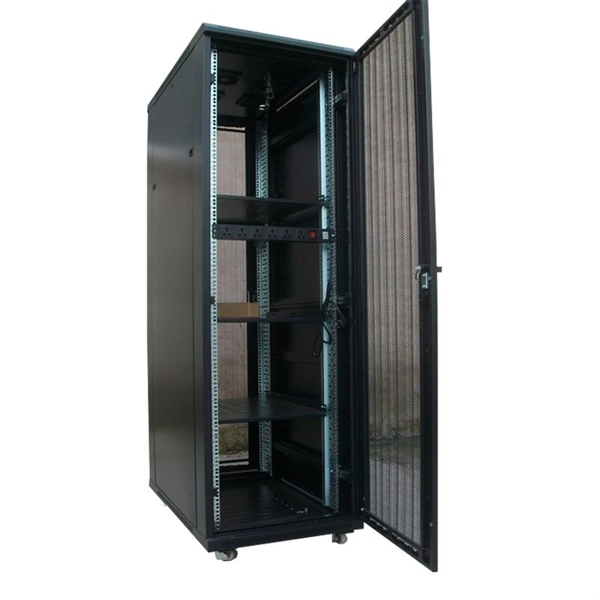
Telecom Racks & Cabinets
19-inch racks, wall-mount cabinets, open frames with high load capacity and seismic rating.
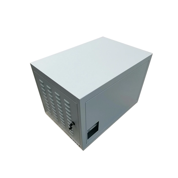
Outdoor Climate Cabinets
IP55/IP66 outdoor enclosures with integrated cooling/heating, -40°C to +55°C operation.
Smart PDUs & Power Distribution
Intelligent PDUs with remote monitoring, per-outlet switching, and environmental sensors.
Shelters & Network Cabinets
Prefabricated telecom shelters, emergency comms shelters, and network cabinets with cable management.