Protective Relay Basics
Relay curves show only the time for the relay itself to operate and do not include additional time required to trip and clear the fault. The relay curve is shown as the dark blue line.
Understanding Protection Relays: 50, 50N, 51, and 51N
Combines time delay with neutral/ground overcurrent detection. Also may be directional for selective tripping. Understanding these relay functions is essential for effective power system
Instantaneous and Time-overcurrent (50/51) Protection
Time overcurrent protection is where a protective relay initiates a breaker trip based on the combination of overcurrent magnitude and overcurrent duration, the relay tripping sooner with greater current
Inverse Time Overcurrent Relays and Curves Explained
The time it takes for the relay to trip will vary depending on the curve slope. These curves can be used by engineers to coordinate with other protective devices upstream for selectivity and
Pick Up Current | Current Setting | Plug Setting Multiplier and Time
Time Setting Multiplier (TSM): Adjusts the relay''s operating time by setting how quickly the relay contacts close. Time vs. PSM Curve: Shows the relationship between relay operating time
Distribution Automation Handbook
The operating time of definite time relays does not depend on the magnitude of the fault cur-rent, while the operating time of inverse time relays is shorter the higher the fault current magnitude is. The time
Types of Overcurrent Relay
The relay exhibits an inverse relation between operating time and fault current near pick-up value and becomes almost constant just above the pick-up value. IDMT relays are widely used for
What is Time Grading in Relay Protection
All of the following operational timeframes are taken into account into the minimum time interval between the relay characteristics: It takes at least 0.4 seconds for the relay to activate, the
Power System Protective Relays: Principles & Practices
As the protected components of the electrical systems have changed in size, configuration and their critical roles in the power system supply, some protection aspects need to be revisited (i.e. the use of
Time selective protection
R time needed to cancel the trip. tM = Delay of an auxiliary relay (if used) ion due saturation of CT. In theory this could be same as the time constant of DC-component. In practice 20 ms is enough
IEC Standard for Relay Coordination – Complete Guide to Protection
The IEC standard for relay coordination recommends time grading between relays based on fault current magnitude and operating characteristics. For overcurrent protection, a minimum time
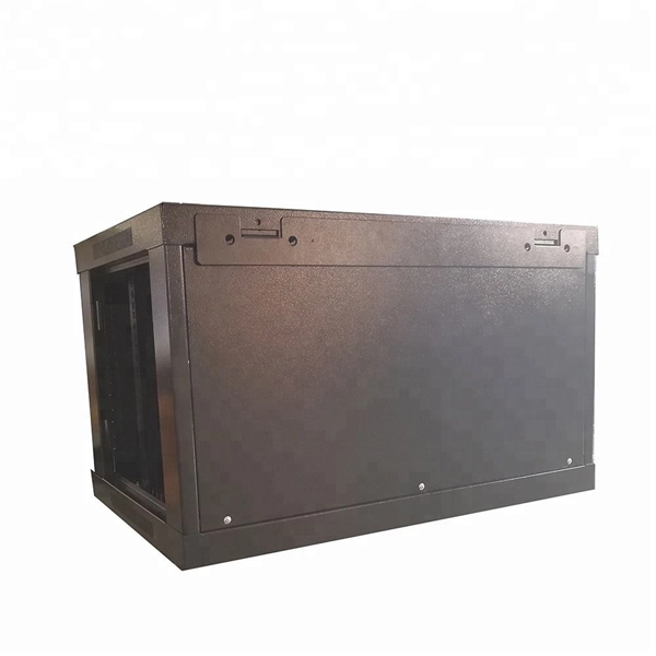
Telecom Racks & Cabinets
19-inch racks, wall-mount cabinets, open frames with high load capacity and seismic rating.
Outdoor Climate Cabinets
IP55/IP66 outdoor enclosures with integrated cooling/heating, -40°C to +55°C operation.
Smart PDUs & Power Distribution
Intelligent PDUs with remote monitoring, per-outlet switching, and environmental sensors.
Shelters & Network Cabinets
Prefabricated telecom shelters, emergency comms shelters, and network cabinets with cable management.