Precautions for Cable Tray Installation
When two sets of cable trays are installed on the same beam, the net distance between the two sets of cable trays should not be less than 50 mm. When multi-layer installation of cable trays for laying
A Guide to Installing and Supporting Electrical Cable Trays
A professional guide to installing electrical cable tray systems per NEC Article 392. Covers support, securing cables, and fill calculations.
Cable Tray Support Spacing: Key Guidelines Explained
Explore the essential cable tray support spacing requirements for safe and efficient installations. Learn NEC guidelines for perforated, ladder, and wire mesh trays.
Core Principles for Electrical and Instrumentation Cable Tray Layouts
Spacing Standards: Electrical (power) and instrumentation (signal/control) cable trays should maintain a minimum vertical and horizontal distance. Industry standards often recommend at least 300mm (12

Best practice guide to cable ladder and cable tray
Cable ladder and cable tray systems The following recommendations are intended to be a practical guide to ensure the safe and proper installation of
GUIDE CABLE TRAYS TECHNICAL
In accordance with its continuous impro-vement policy, Legrand reserves the right to change the specifications and illus-trations without notice. All illustrations, descriptions and technical information
CABLE TRAY SYSTEMS GUIDE
Some applications may require the cable tray to support the weight of a single, dead object in addition to the cable loads. Specifications typically require this to be applied at the midpoint of the span between
Cable Tray Installation Rules (NEC 392) – Electrical Trader
Generally, standard trays require supports every 6 to 10 feet, while heavy-duty, long-span trays can handle distances of up to 20 feet between supports. To determine the proper spacing,
Cable Tray Spacing Standards for Installation and Safety
Discover the essential cable tray spacing requirements for safe and efficient installation. Learn key standards, horizontal and vertical spacing, and more.
Cable Tray Technical Guide A practical guide to product selection
Cable tray length is selected based on the load to be supported, the distance between the supports (also referred to as the span), and handling and installation constraints.
INSTALLATION GUIDE
To maximize the rigidity of the ladder tray, the section should be laid out so that the splice locations are between the quarter point of the tray [1.5 meters (4.8'') for a 6 meter section] and the location of the
Telecom Racks & Cabinets
19-inch racks, wall-mount cabinets, open frames with high load capacity and seismic rating.
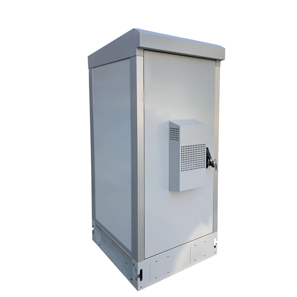
Outdoor Climate Cabinets
IP55/IP66 outdoor enclosures with integrated cooling/heating, -40°C to +55°C operation.
Smart PDUs & Power Distribution
Intelligent PDUs with remote monitoring, per-outlet switching, and environmental sensors.
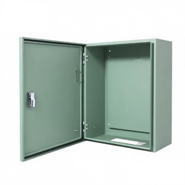
Shelters & Network Cabinets
Prefabricated telecom shelters, emergency comms shelters, and network cabinets with cable management.