Guide to cable support systems
The load capacity of the cable trays according to the support width can be read off in the diagram using load curves – here, shown as an example for a cable tray with the tray widths 100 to 600 mm.
Ladder Trays | Cable Tray and Reels | Wire and Cable Management
Refers to the approximate height of a cable tray used for specifying. Selecting a specific height will show cable trays with that height, as well as cable tray accessories compatible with that height.
B-Line series Cable Tray Design Considerations
Our wind certification report provides you with list of acceptable B-Line series cable tray supports, fittings and covers based off of the environmental conditions, cable loading, and type of cable tray in your
Decoding Cable Tray Support Structures: Tips and Insights
Discover efficient cable tray support structures for optimal cable management. Learn about hanger, wall-mounted, and Unistrut systems for safer installations.
Cable Tray Systems & Support Brackets | TechLine Mfg
Supports should be located so that connectors (splice joints) between horizontal runs fall between the support point and quarter point of the span. The Support Span should not be greater than the straight
GUIDE CABLE TRAYS TECHNICAL
When fitting cable trays and their accessories, the products are cut on site to create changes of direction, adjust sections, etc. Damage can also occur during handling; as a result, both the
Cable Tray Installation Details | PDF | Hvac | Machines
This document contains reference information for typical cable tray support details, including cable tray data sheets, cable lists, and HVAC system specifications for
CABLE TRAY SYSTEMS GUIDE
The design and cost of the cable tray is greatly affected by this designation. In order to determine the most appropriate and economical system, a class should be selected that reflects the actual total
Cable Tray Technical Guide A practical guide to product selection
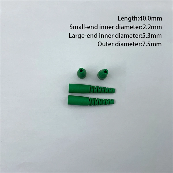
Cable tray length is selected based on the load to be supported, the distance between the supports (also referred to as the span), and handling and installation constraints.
A Guide to Installing and Supporting Electrical Cable Trays
This guide covers the critical steps, from selecting the right electrical cable tray and performing accurate cable fill calculations to managing a safe cable pull through and ensuring all bonding and grounding
Best Practice Guide to Cable Ladder and Cable Tray Systems
This guide covers cable ladder systems, cable tray systems, channel support systems and associated supports intended for the support and accommodation of cables and possibly other electrical
Installation Guide
The ends of the tray fit into channels at the margins of the NoSplice support, then (supplied) Ground Splice is secured to the support. When utilizing the NoSplice, supports must be placed approximately
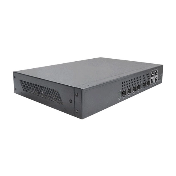
Telecom Racks & Cabinets
19-inch racks, wall-mount cabinets, open frames with high load capacity and seismic rating.
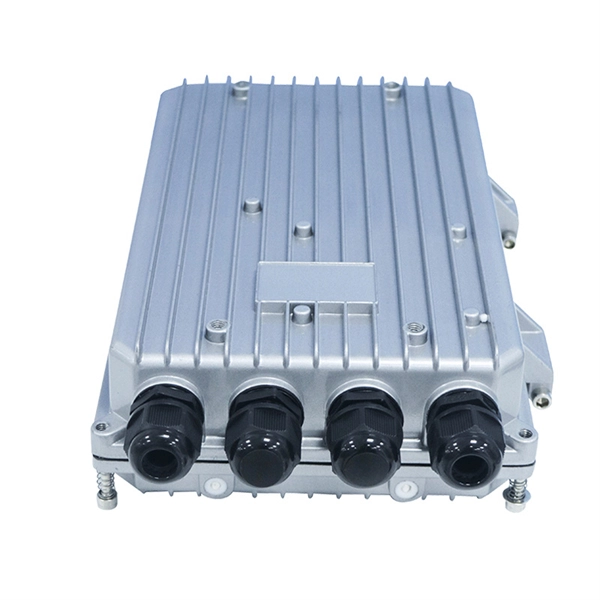
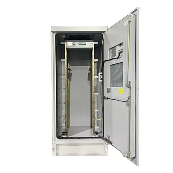
Outdoor Climate Cabinets
IP55/IP66 outdoor enclosures with integrated cooling/heating, -40°C to +55°C operation.
Smart PDUs & Power Distribution
Intelligent PDUs with remote monitoring, per-outlet switching, and environmental sensors.
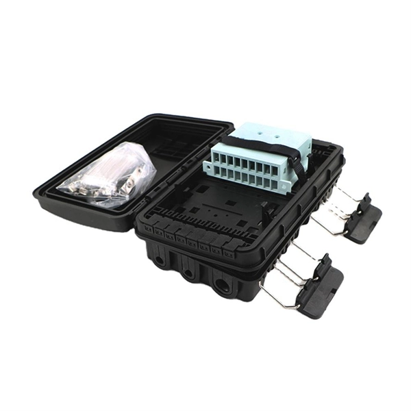
Shelters & Network Cabinets
Prefabricated telecom shelters, emergency comms shelters, and network cabinets with cable management.