-
Cable trays can be run along the lower part of the wall
You can run cable trays transversely through partitions and walls or vertically through platforms and floors if the installations, complete with installed cables, conform to Sec. 18 (D)]; that is, those installations are made such that the possible spread of. The primary rulebook used in the safe use of cable trays is NEC Article 392. This is a description of how to select, install, and support these metal or plastic frames, on which electrical wires are installed. A well-planned cable tray installation not only organizes conductors but also provides protection and makes future. Cable trays can be used as a support system for various wiring methods, including service conductors, feeders, branch circuits, communications circuits, control circuits, and signaling circuits (392. Cable trays are used not just in industrial establishments.
[PDF Version]
-
National Standard Optical Cable Sheath Wall Thickness
Fiber optic "cable" refers to the complete assembly of fibers, other internal parts like buffer tubes, ripcords, stiffeners, strength members all included inside an outer protective covering called the jacket. The optical fiber color coding shall be in accordance with EIA/TIA-598, "Optical Fiber Cable Color Coding. (FOA) was founded in 1995 to help develop the workforce to build the fiber optic networks to support a rapid expansion in communications and the Internet. The charter of the FOA was to promote professionalism in fiber optics through education, certification, and. However, when I started trying to find out where I got it from, it turned out that there were no requirements for sheath thickness in the IEC standards for HV and EHV cables. ASTM E119, Standard Test Methods for Fire Tests of Building Construction and Materials, is the test standard for determining the. This is the standard sheathing material for cables for outdoor use. It has excellent weathering resistance.
[PDF Version]
-
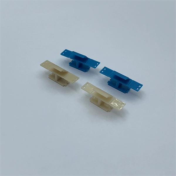
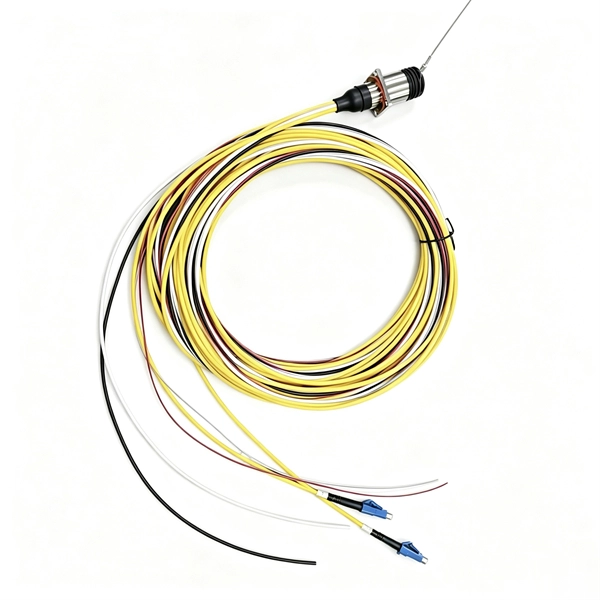
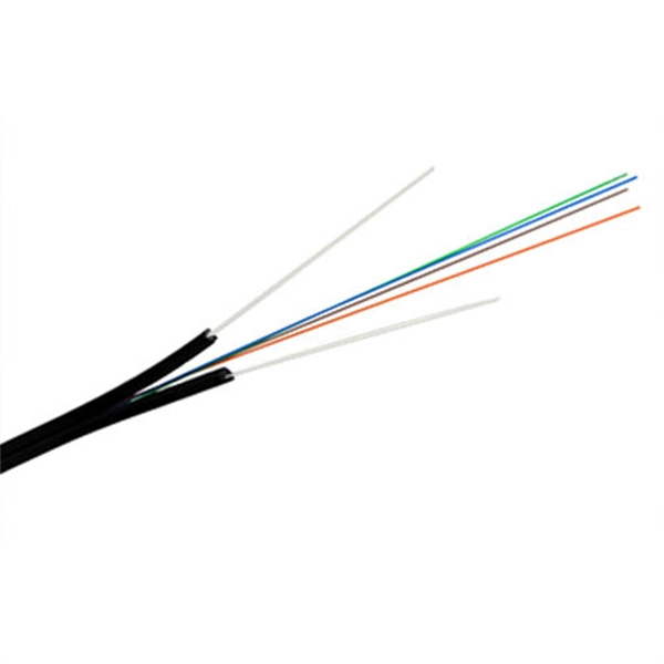
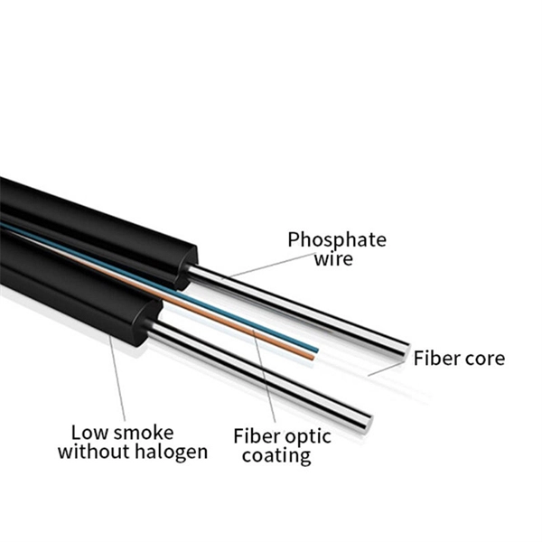
Butterfly-shaped fiber optic cable drop sleeve through the wall
Ideal for residential buildings, offices, and data centers, this drop cable offers flexibility, durability, and easy handling. Easy-Strip Design: The unique “butterfly” flute allows for rapid jacket removal, making it perfectly compatible with field-installable Fast. The Butterfly Flat Indoor FTTH Drop Cable is an advanced fiber optic solution for indoor Fiber-to-the-Home (FTTH) installations. Its flat design allows for efficient and space-saving deployment, particularly in areas where space is limited. The optical fiber core is located in the center of the cable body, two reinforcing cores are placed on both sides, and the outer layer is enveloped and sheathed to form a cable. Two steel wired or FRP are placed at the two sides. With small diameter, water-resistant, the non-metallic. With easy accessibility to the fiber and simple installation, FTTH cable can be directly connected to the homes.
[PDF Version]
-
The fiber optic cable is too close to the wall
Mark the cable paths and make sure you're not placing fiber too close to high-voltage wiring, heat sources, or anything that might cause interference. Always double-check your plan against local electrical codes. Some common prep steps include: Not all fiber cables are. Running fiber internally involves extending this high-speed link from the service entry point to a centralized location, such as a dedicated media closet or network rack. This DIY effort is undertaken to maximize performance, improve aesthetics, or relocate the Optical Network Terminal (ONT) to a. This terminated in a reel of cable (about an extra 30m). I have looked at the bit installed by the provider, but I cannot tell how it was done. The best way to avoid problems down the line is to start with a site survey. Walk the space, take real measurements, and identify physical barriers like existing conduit, HVAC ducts, or. Proper fiber optic cable installation is critical to ensuring network performance and long-term reliability.
[PDF Version]
-
Fiber optic cable withstands pressure when passing through a wall
Crush proof armored cable is engineered to withstand intense physical force. Unlike traditional builds, it includes a metal or corrugated steel layer that shields the core fibers from mechanical damage. While the glass fibers inside are fragile, modern fiber cables are engineered to withstand crushing forces, extreme temperatures, and even rodent attacks—making them vital for. Properly designed fiber optic cables ensure maximum transmission performance and network reliability. Critical design factors include pulling strength limits, bend radius guidelines, water protection, and fire rating compliance, among others. LYNN's Pushable/Pullable Bullet Fiber will debut at CEDIA Expo September 7. LYNN says the preterminated fiber-optic cable “is ideal for wiring telecom connections and demarcation locations in residential, commercial. Fiber optic "cable" refers to the complete assembly of fibers, other internal parts like buffer tubes, ripcords, stiffeners, strength members all included inside an outer protective covering called the jacket. The light pulses travel for many miles before they start to.
[PDF Version]
-
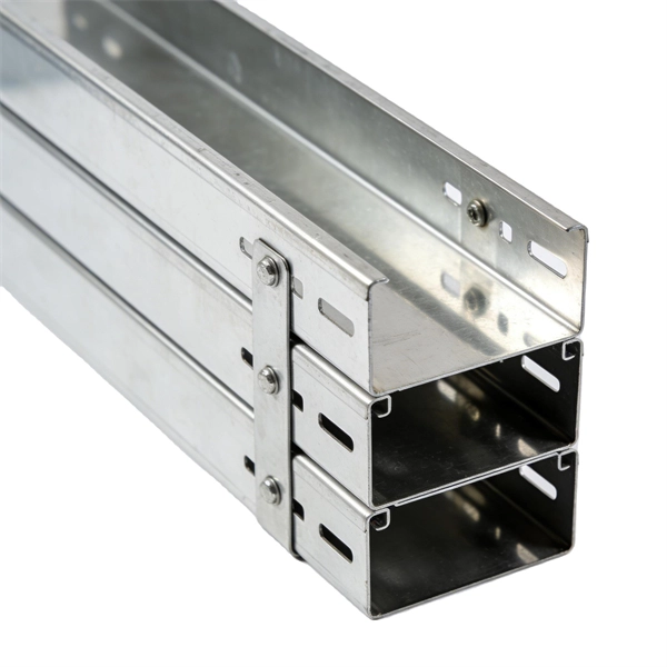
Erection of cable tray support against the wall in vertical shaft
Support Methods: Common support methods include trapeze hangers, which are used for ceiling suspensions, and cantilever wall brackets, which are mounted directly to walls for runs along vertical surfaces. The choice depends on the building structure and the planned. An electrical cable tray system serves as a rigid structural raceway designed to support and route electrical cables and wires. Unlike a simple wire trough, which is typically a covered channel for shorter runs, cable trays provide a comprehensive support system for complex wiring paths over long. Wall-mounted supports are used for situations where cable trays need to be attached to a wall. This method was prepared in reference to scope of work as guideline for effective enforcement of work. Neglecting installation and maintenance guidelines may lead to a personal injury as well as damage to property.
[PDF Version]
-
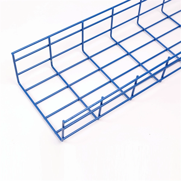
Indoor cable trays installed along the wall
This guide provides step-by-step instructions on installing a cable tray on a wall, covering different types of cable trays, tools needed, and safety tips. In this case, hiding your cables by installing the cables inside the walls is the better option as this will completely hide them from view and unintentional tampering. The guide includes diagrams for mounting cable trays on walls using pre-fabricated flanges or channels, laying cables, and selecting the. This guide covers the critical steps, from selecting the right electrical cable tray and performing accurate cable fill calculations to managing a safe cable pull through and ensuring all bonding and grounding requirements are met. Our knowledgeable production team works closely with each customer to provide quality solutions based on your schedule and budget. The following pages address the 2014 National Electrical Code® requirements for cable tray systems as well as design solutions from practical experience. The information has been organized for.
[PDF Version]
-
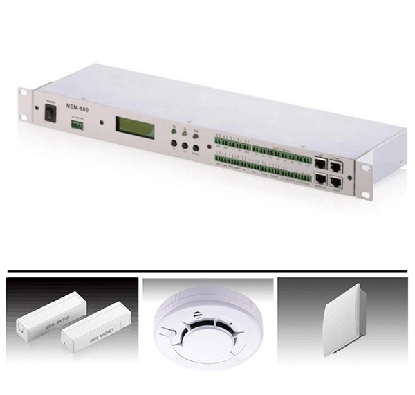
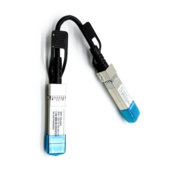
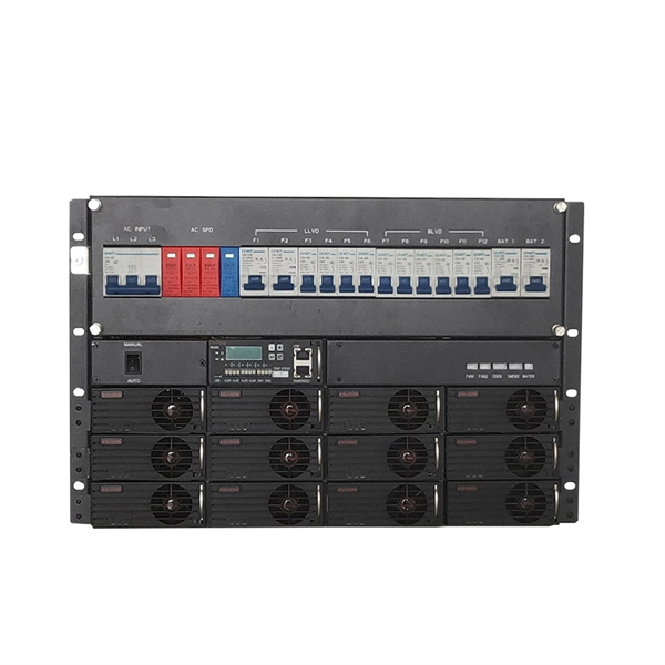
Modular energy storage cabinet remote monitoring technology support vs copper cable vs fiber optic cable
This article delves into the technical comparison between copper and fiber optic cables, exploring their unique properties, applications, and potential drawbacks. When energy storage cabinet remote systems prevented a 72-hour blackout in Texas last month, industry leaders finally stopped asking "if" and started asking "how fast". Copper cables are renowned for their superior conductivity, making them the. ocations are often difficult to reach and it might be too late to remedy the fault. Fiber has nearly unlimited bandwidth -- so once you deploy it, you can trust that it will outpace consumer demand for decades to come.
[PDF Version]
-
Calculation of distance from cable tray bend to wall
Calculate horizontal, vertical, or compound cable tray offsets based on bend angle, offset distance, and available installation space. Measure this distance along the straight tray. Two Bends Per Offset: Every offset requires two equal bends — one to move laterally and one to return to parallel. The total tray section consumed = 2 × single bend length. Pre-fab vs Field Bent: For standard offsets (6, 12, 18 in at 45°), use manufacturer pre-fabricated offset fittings to save. When installing two cable trays in parallel at the same height, the distance between them should be no less than 0. This spacing is crucial for adequate maintenance access, ease of inspection, and ensuring proper airflow for effective heat dissipation. ) that matches or exceeds this value. 8 (Other Mechanical Stresses (AJ)) in that document provides requirements for cable support. IEC 61537 covers cable tray and cable ladder systems for the support and accommodation of cables, while NEC Article 392 governs cable.
[PDF Version]
-
Angle iron is used to fix the cable tray against the wall
Angle steel supports are a more traditional and reliable choice for electrical cable tray support. Angle iron with lengthwise/longitudinal slots 7x30mm on one side for universal support. Edges and bolt holes are not rounded or otherwise prepared. Taking the grid cable tray and accessories of new sunpln Technology as an example, first we need to determine which type of accessories we use. This Wall Angle Support, LWASK24BLK item fits 24. 00 with a material of Steel color Black. Wasn't sure how well that might work or if anyone has run into that before and has advice on how they fixed it. Any. Welcome to our comprehensive guide on installing wall brackets for different types of cable trays and cable ladders! In this video, we will walk you through the installation process for four different types of wall brackets, specifically designed for cable trays, mesh cable trays, and cable.
[PDF Version]
-
How to mount communication cables on a cable management rack
In this video, we'll walk you through tools, techniques, tips, and mistakes to avoid when organizing Ethernet cables, patch panels, switches, and power units in your network rack. Organizing cable management within a rack simplifies network device access and makes it easier to track cables during installation. FS. Tools: cable management clips, cable managers, cable tray fasteners, cable clips, cable ties, electrical tape, RJ45 connectors, and a complete set of cable processing equipment. Especially Important: Labeling tags 2. Use tools for cable management instead of hands. By following a few simple steps, you can ensure that your server rack is not only aesthetically. Structured cabling is the foundation of an efficient network environment, ensuring stable performance and easy scalability. As businesses increasingly rely on robust network infrastructure, proper cable organization becomes critical for.
[PDF Version]
-
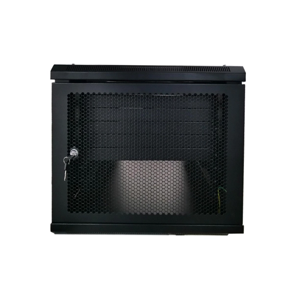
Recommended Brands of Cabinet Cable Management Racks
So, other than making your server rack look nice, why is good cable management so important? There are actually a number of reasons. Some are more hardware-related, while others are related t.
[PDF Version]
-
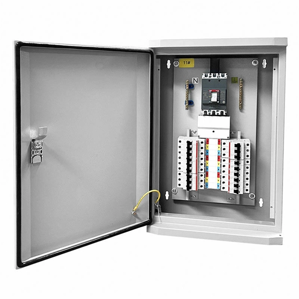
Thickness of cable tray wall penetration sealing
Where cables pass through shafts, walls, slabs, or enter electrical panels or cabinets, openings shall be tightly sealed with firestopping materials in accordance with design requirements. Process flow: reserved openings → busway installation → distribution box positioning and installation →. WSP weatherstops are designed to seal penetrations of any type in walls or floors by cable tray, cable conduit, pipe and/or bus duct. The WSP system utilizes a powder coated or galvanized steel frame that encompasses the entire tray or duct at the point of penetration. * Two (2) sticks of moldable putty (part number FSP-MPS) are also needed for each opening. UL Listed Systems Concrete Wall - C-AJ-4056 3 HR F-Rating, 3/4 HR T-Rating Gypsum. fire exposure to roof tests. A rung spacing of 6 to 9 inches (150 to 230 mm) is preferable when the cable tray cont d for instrumentation and control applications that require.
[PDF Version]
-
How to pull the pigtail cable out of the wall
If you remove the gap seal it should be trivial to pull it out. I would dig around the cable on the exterior side with a knife or pliers to free up the cable. Electrician: How do I pull wires in walls and ceilings? Can I use a metal coat hanger for wire pulling? Answer: Several methods and tools are available for wire pulling in walls and ceilings. Drawing by Martha Garstang Hill. Is there a method to do this or do I just pull it with force? The old cable was connected to a TV satellite dish outside that was removed, but the cable was left there. I want to install a security camera outside my house and use. A pigtail connector acts as a bridge, joining multiple wires together or connecting a wire to a terminal. Whether you're a licensed electrician, electrical apprentice, or DIY enthusiast — this is the wire-pulling technique pros. How to pull pigtail from dual charge cord? I would like to switch the 120v pigtail cord on my new Ultium dual charge cord to put in the 220v pigtail cord but I can't pull it out. I wish this had a release button but I.
[PDF Version]
-
Calculation formula for cable tray supports and hangers
Cable tray support quantity can be calculated using a simple formula: Support Quantity = Total Length ÷ Support Spacing + 1 20 ÷ 2 + 1 = 11 supports In a typical project, a 20-meter cable tray with 2-meter spacing requires 11 supports. As a key structure supporting the cable tray, the accurate calculation of the support quantity directly affects construction costs, efficiency, and safety. Follow these simple steps: Define Tray Dimensions: Enter the width and depth of your planned cable tray (in mm or inches). Select Fill Standard: Choose 40% for power cables (NEC compliant) or 50% for. The formula to calculate the cable tray capacity is: [ CTC = text {floor}left (frac {W cdot H cdot FR} {CA}right) ] Where: ( CTC ) is the cable tray capacity (number of cables). This article details everything from permitted uses and cable types to fill capacities and. Table 1: IEC Common Ladder and Tray Dimensions Note: Quantities above are approximate and assume single-layer horizontal mounting without fill derating. The International Electrotechnical Commission (IEC).
[PDF Version]
Telecom Racks & Cabinets
19-inch racks, wall-mount cabinets, open frames with high load capacity and seismic rating.
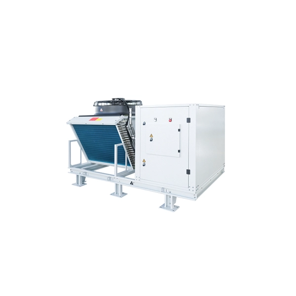
Outdoor Climate Cabinets
IP55/IP66 outdoor enclosures with integrated cooling/heating, -40°C to +55°C operation.
Smart PDUs & Power Distribution
Intelligent PDUs with remote monitoring, per-outlet switching, and environmental sensors.
Shelters & Network Cabinets
Prefabricated telecom shelters, emergency comms shelters, and network cabinets with cable management.