-

How many meters of cable tray plus support
Cable tray support quantity can be calculated using a simple formula: Support Quantity = Total Length ÷ Support Spacing + 1 20 ÷ 2 + 1 = 11 supports In a typical project, a 20-meter cable tray with 2-meter spacing requires 11 supports. This calculator determines the maximum number of cables that can be safely housed within a cable tray based on its dimensions and the cross-sectional area of the cables. Cable tray supports are components used to fix and support. IEC 61537 and IEC 60364 require evaluating tray dimensions based on cable quantity, type, and layout configuration. Below are industry-standard tray and ladder dimensions used globally, based on typical installations and in alignment with IEC 61537:2016 and manufacturer catalogs. IEC 61537 covers cable tray and cable ladder systems for the support and accommodation of cables, while NEC Article 392 governs cable.
[PDF Version]
-

Fabrication and Installation of Cable Tray Supports in Factory Buildings
This guide covers the critical steps, from selecting the right electrical cable tray and performing accurate cable fill calculations to managing a safe cable pull through and ensuring all bonding and grounding requirements are met. Cable tray systems provide a safe, organized, and flexible method for supporting insulated conductors and cables in commercial and industrial electrical installations. When properly selected and installed, cable trays simplify routing, improve accessibility, and support future expansion while. Cable management in buildings and industrial premises is a very important aspect. These guidelines are not intended to cover all details or variations in cable ladder and cable tray. in this document have been tested extens ompetent professional en completely installed, without damage either to conductors or structural system use maintain spacing or to keep cables in place when the tray is ect the minimum bend ra-dius for cables as they exit the bottom of the cable tray. Using the example and guide below, create your.
[PDF Version]
-
Spacing requirements for cable tray corner supports
Typical spacing: Supports every 1. Straight sections: Maximum span should not exceed manufacturer's recommendations. The NEC requires that cable trays must be supported by members at an interval specified by the cable tray manufacturer, but not more than 5 feet for horizontal runs to support the weight of the cables and other loads. The NEC has a requirement for ladder-type cable trays. Proper installation can significantly reduce. Article Summary: A compliant cable tray installation requires a thorough understanding of NEC Article 392, proper structural support, and precise installation techniques. This guide covers the critical steps, from selecting the right electrical cable tray and performing accurate cable fill. maintain spacing or to keep cables in place when the tray is ect the minimum bend ra-dius for cables as they exit the bottom of the cable tray. These systems, made from metal or plastic, are open structures designed to support electrical conductors, ensuring proper organization and safety. It also demonstrates how Eaton's solutions and services can help: As an industry leader in cable tray, Eaton offers one of the widest ranges of.
[PDF Version]
-
How many centimeters is the cable tray support above the ground
Answer: The NEC does not have a specific installation clearance, but indicates in section 318-6 (b) that cable trays should be exposed and accessible. The primary rulebook used in the safe use of cable trays is NEC Article 392. This is a description of how to select, install, and support these metal or plastic frames, on which electrical wires are installed. Here's what you need to know: Cable Types: Only use. Cable Tray Support Span: The distance between supports is a critical calculation. The cable tray support span must be determined based on the manufacturer's load capacity chart and the total anticipated weight of the cables. The National Electrical Code is a set of principles designed to promote public safety and welfare, as well as safeguard public health by regulating the design and operation of electrical facilities and. Solid bottom cable tray: The sum of cable diameters must not be greater than 90% of the allotted cable tray width. Cables Smaller than 4/0 AWG/Kcmil (120 Sq.
[PDF Version]
-
Calculation formula for cable tray supports and hangers
Cable tray support quantity can be calculated using a simple formula: Support Quantity = Total Length ÷ Support Spacing + 1 20 ÷ 2 + 1 = 11 supports In a typical project, a 20-meter cable tray with 2-meter spacing requires 11 supports. As a key structure supporting the cable tray, the accurate calculation of the support quantity directly affects construction costs, efficiency, and safety. Follow these simple steps: Define Tray Dimensions: Enter the width and depth of your planned cable tray (in mm or inches). Select Fill Standard: Choose 40% for power cables (NEC compliant) or 50% for. The formula to calculate the cable tray capacity is: [ CTC = text {floor}left (frac {W cdot H cdot FR} {CA}right) ] Where: ( CTC ) is the cable tray capacity (number of cables). This article details everything from permitted uses and cable types to fill capacities and. Table 1: IEC Common Ladder and Tray Dimensions Note: Quantities above are approximate and assume single-layer horizontal mounting without fill derating. The International Electrotechnical Commission (IEC).
[PDF Version]
-
Installation of Seismic-Resistant Cable Tray Supports in Tajikistan
This study aims to develop a simple yet efficient performance-based design optimization methodology for cable tray systems in building structures. In the paper, the drift ratio between adjacent supports i.
[PDF Version]
-
Where in Germany can I get cable tray support installation services
144 Companies and suppliers for cable trays ✓Find wholesalers and contact them directly ✓Leading B2B martketplace ➤ Find companies now!144 Companies and suppliers for cable trays ✓Find wholesalers and contact them directly ✓Leading B2B martketplace ➤ Find companies now!. WDM Deutenberg offers you state-of-the-art and corrosion-resistant cable trays. Lichttechnik Hessling has been one of the leading electrical service specialists for industry and plant. Cable trays are an integrated, highly flexible cable support system when used in combination with the matching support structures, covers and system-specific accessories. Their innovative devices and extensive catalog ensure modern and efficient electrical installations. Rosenberger OSI is a specialist in. Germany is home to several leading cable tray manufacturers renowned for their precision engineering and high-quality products. 5 mm thick steel wires welded together.
[PDF Version]
-
How much does a cable tray support arm cost in the UAE
Buy cable tray supports suitable for industrial, commercial, and domestic wiring. Order online for 5% discount. Listed below are the Top Cable Tray Suppliers in UAE, offers different types of cable trays to business these include - electrical cable tray, industrial cable trays, plastic cable trays, cable tray trunking, stainless steel cable trays, ladder cable trays, wall mounted cable tray bend with control. Browse our range of high-quality cable tray supports. Our specialty is providing a broad selection of high-quality cable basket accessories to fit the different demands of different sectors of the economy. Cabling rack connector can be used as ground support and fixed, or can be installed on the top of the cabinet as a cabinet support.
[PDF Version]
-
Requirements for Spacing of Fire Cable Tray Supports
Cable Management Tray Size: Choose a tray size that will hold the desired amount and length of cable. Although BS 7671 touches on the subject of cable supports, it does not detail specifically what these support distances should be. Clause 522-08-04 Where conductors or cables are not supported. The spacing between trays, whether horizontal or vertical, depends on various factors like cable type, environment, and tray material. Proper installation can significantly reduce electromagnetic interference, prevent fire hazards, and improve overall efficiency. This article provides an in-depth. Senior Electrical Engineer, QA/QC Supervisor,Electrical Specialists, Sr QA/QC engineer or inspector, E&I Engineer QMS-ISO-9001-2015 (CQI-IRCA) Registered With SCE --QMS-ISO®️️ Lead Auditor RC,NEOM and SEC Approved 1. Here's what you need to know: Cable Types: Only use. Support Methods: Common support methods include trapeze hangers, which are used for ceiling suspensions, and cantilever wall brackets, which are mounted directly to walls for runs along vertical surfaces.
[PDF Version]
-
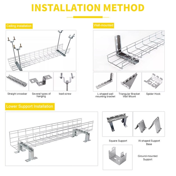
Erection of cable tray support against the wall in vertical shaft
Support Methods: Common support methods include trapeze hangers, which are used for ceiling suspensions, and cantilever wall brackets, which are mounted directly to walls for runs along vertical surfaces. The choice depends on the building structure and the planned. An electrical cable tray system serves as a rigid structural raceway designed to support and route electrical cables and wires. Unlike a simple wire trough, which is typically a covered channel for shorter runs, cable trays provide a comprehensive support system for complex wiring paths over long. Wall-mounted supports are used for situations where cable trays need to be attached to a wall. This method was prepared in reference to scope of work as guideline for effective enforcement of work. Neglecting installation and maintenance guidelines may lead to a personal injury as well as damage to property.
[PDF Version]
-
Cable tray support pull-out calculation
Cable tray support quantity can be calculated using a simple formula: Support Quantity = Total Length ÷ Support Spacing + 1 20 ÷ 2 + 1 = 11 supports In a typical project, a 20-meter cable tray with 2-meter spacing requires 11 supports. Helps determine the proper wire size for an electrical circuit based on the voltage drop and current carrying capacity of an electrical circuit. Follow these simple steps: Define Tray Dimensions: Enter the width and depth of your planned cable tray (in mm or inches). Select Fill. Cable Information: Location: Engineer: #/Cond. Sum Area (in^2) Comments Maximum allowable tray fill per Area (in^2) Tray Design Depth = Sum of OD (in) Total Cross Sectional Areas of all cables: Total Sum of the Diameters: in. The right cable tray sizing calculator helps engineers turn cable schedules into a verified tray width and fill check before material ordering and site installation. Open the full calculator for the best experience.
[PDF Version]
-
Lateral spacing of cable tray supports
Support spacing for cable trays must align with the manufacturer's instructions, as outlined in NEC 392. Generally, standard trays require supports every 6 to 10 feet, while heavy-duty, long-span trays can handle distances of up to 20 feet between supports. The National Electrical Code (NEC) covers many aspects of cable tray supports and fittings. The National Electrical Code is a set of principles designed to promote public safety and welfare, as well as safeguard public health by regulating the design and operation of electrical facilities and. The spacing between trays, whether horizontal or vertical, depends on various factors like cable type, environment, and tray material. Unlike a simple wire trough, which is typically a covered channel for shorter runs, cable trays provide a comprehensive support system for complex wiring paths over long. Hubbell Wiring Device-Kellems and Hubbell Premise Wiring are divisions of Hubbell Incorporated, a U.
[PDF Version]
-
Zimbabwe cable tray support manufacturer
We, one of the well-known Ladder Cable Trays Suppliers and Exporters from Zimbabwe, offer a comprehensive range of cable trays manufactured using high-quality materials to ensure strength, durability, and corrosion resistance. Contact us today to discuss your ladder. Started back in 1983, Cable House is a recognized name engaged in manufacturing and supplying wide range including Hose Clamps, Cable Ties, Crimping Tools, Cable Tray, Industrial Connectors and more, to the national as well as the international market. With our manufacturing expertise, we have even. Keep your cables safe and organized with Brilltech Engineers Pvt. We offer top-notch Galvanized Cable Trays in Zimbabwe. These metal trays, coated with a special zinc shield, resist rust and last a long time, even in tough environments. We believe in building fruitful business partnerships.
[PDF Version]
-
Spacing of T-type cable tray supports
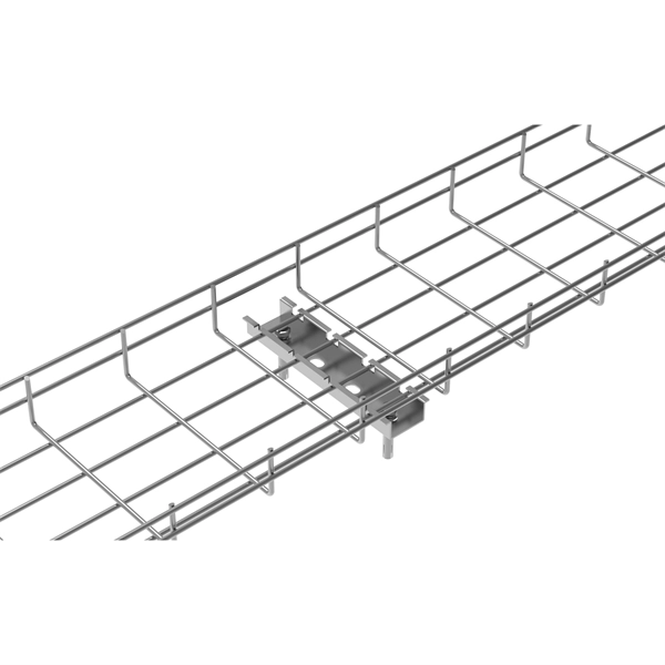
Cable Management Tray Size: Choose a tray size that will hold the desired amount and length of cable. The National Electrical Code (NEC) covers many aspects of cable tray supports and fittings. The National Electrical Code is a set of principles designed to promote public safety and welfare, as well as safeguard public health by regulating the design and operation of electrical facilities and. maintain spacing or to keep cables in place when the tray is ect the minimum bend ra-dius for cables as they exit the bottom of the cable tray. A rung spacing of 6 to 9 inches (150 to 230 mm) is preferable when the cable tray cont d for instrumentation and control applications that require. Understanding cable tray spacing is key to meeting safety regulations and maintaining system performance. Proper installation can significantly reduce. When developing our cable support OBO can offer reliable solutions for systems, three attributes are at the routing and fastening cables securely core of what we do: efficiency, resil- for each of these installation challeng-ience and safety. es in the industrial environment. The Ladder Tray features light, rugged, tubular steel construction.
[PDF Version]
-
Calculation of cable tray support force
Cable tray support quantity can be calculated using a simple formula: Support Quantity = Total Length ÷ Support Spacing + 1 20 ÷ 2 + 1 = 11 supports In a typical project, a 20-meter cable tray with 2-meter spacing requires 11 supports. The all-in-one desktop software for cable tray sizing, fill rate analysis, bracket design, seismic verification, and thermal expansion calculations. Fully compliant with IEC, BS, NEC, VDE, and AREI standards. From initial sizing to final documentation — one tool handles it. Using our advanced cable tray load calculator is simple and ensures your electrical installation meets structural and safety standards. This calculator features an interactive interface with advanced visualizations.
[PDF Version]
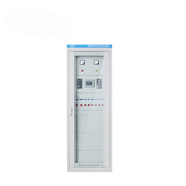
Telecom Racks & Cabinets
19-inch racks, wall-mount cabinets, open frames with high load capacity and seismic rating.
Outdoor Climate Cabinets
IP55/IP66 outdoor enclosures with integrated cooling/heating, -40°C to +55°C operation.
Smart PDUs & Power Distribution
Intelligent PDUs with remote monitoring, per-outlet switching, and environmental sensors.
Shelters & Network Cabinets
Prefabricated telecom shelters, emergency comms shelters, and network cabinets with cable management.