-
Is a junction box a fusion splice box
A splice box, also known as a junction splice enclosure or splice enclosure, serves a similar purpose to a junction box, but with some notable differences. While both boxes facilitate the connection of wires, splice boxes are primarily used for joining or. A junction box, commonly referred to as a J-box, is the formal and universally recognized component for enclosing wire connections in standard electrical systems. It contains and protects electrical splices, taps, and conductor terminations, preventing accidental contact and insulating connections. Junction boxes and splice boxes are both commonly used in electrical systems, but many people are often confused about the differences between these two types of boxes. They are essential for extending circuits, branching power, and protecting wire splices 9. It offers the functions of mechanical/fusion splicing, splitting, and distribution, and can achieve cable straight-through and branch connection. How to Wire a GFCI Outlet without a Ground Wire in an Older Home. And that can be useful if you want to branch off to multiple receptacles or lights.
[PDF Version]
-
How to splice multi-core cables in an optical fiber fusion splicer
Learn how to splice fiber optic cable using fusion splicing with this complete step-by-step guide. 652), cost analysis, and FAQs for network engineers and installers. In this guide, you will find a chronological description of the fusion splicing process, the principal technical standards, and answers to the real-life questions network engineers and procurement teams may have. The guide provides the complete workflow, covering safety precautions, tool selection, fiber preparation, fusion operation, quality control, and. With this in mind, we have prepared the ultimate guide on how to use a fusion splicer on fiber optic cables. more Watch a real technician demonstrate how.
[PDF Version]
-
Where to plug the fusion splice splitter
Please use a dedicated three-wire grounded AC power line, AC / DC power adapter. When the adapter input cable is connected to AC220V, 50 / 60HZ power supply, the user must use an effectively grounded three-holes socket. In this comprehensive guide, we will delve into when and why you need to splice fiber optic cables, discuss how you can maintain cleanliness during the process, and walk you through the steps of fusion splicing, step by step. The guide covers everything from basic principles of fusion splicing to detailed procedures; it is intended to provide both newbies and professionals with the necessary knowledge and skills. A fiber fusion splicer is an instrument designed to permanently connect two optical fibers by fusing their ends together using heat. This process creates a seamless joint, allowing light signals to pass through with minimal attenuation. Failure to comply with any of the instructions or warning contained in the User's Manual is a direct violation of the design, manufacture and intende standard use of the instrument.
[PDF Version]
-
Reasons for misconnection in pigtail fusion splicers
Get the wrong connector type, the wrong polish, or skip proper fusion splicing technique—and you're looking at elevated signal loss, increased back reflection, and a field termination that fails certification. INNO fusion splicers are designed to actively support technicians working in real-world conditions. Many of the errors reported by the splicer can be corrected quickly and easily, once you. Executive Summary: A fiber optic pigtail is one of the most commonly specified yet least understood components in structured cabling. When properly maintained and operated, they produce low-loss, high-strength splices. While the Sangken Splicing machines are designed for high-precision work, even the best equipment requires proper troubleshooting when splices fall outside of. Fiber optic fusion splicers require precise operation. Fiber contamination Alignment error messages.
[PDF Version]
-
What are some manufacturers of fusion splice multimode optical cables
Fujikura Europe Ltd offers fusion splicers, which are essential for efficiently joining optical fibers. The fully ruggedized 45S fusion splicer comes with a single fiber stripper, 1 pair each FH-70-250 and FH-70-900 fiber holders, set plates, spare electrodes (pair), AC adapter, BTR-17 battery pack, power cord, USB cable, work tray, and carry case. AFL offers a wide range of fiber optic solutions to support the Industrial Market. With its vertically-integrated operations, AFL has the expertise to maximize the performance and scalability of your. Underground communication, aerial hardware, bridge conduit systems, splicing accessories, and communication cables are available. They combine the benefits of fusion splicing with the simplicity of a field-installable connector to expand options for field termination and improve installation performance and reliability over mechanical splice. When terminated with FASTSPLICE Universal Ferrule Splice Holders, these fiber connectors are compatible with the most popular fusion splicers, including AFL, Sumitomo, and FITEL.
[PDF Version]
-
How to coil fiber optic cables in a fusion splice spool
Learn how to splice fiber optic cable using fusion splicing with this complete step-by-step guide. 652), cost analysis, and FAQs for network engineers and installers. In this guide, you will find a chronological description of the fusion splicing process, the principal technical standards, and answers to the real-life questions network engineers and procurement teams may have. The technique for removing the coating involves mastering the "steady, even, and quick" approach. The guide provides the complete workflow, covering safety precautions, tool selection, fiber preparation, fusion operation, quality control, and. With this in mind, we have prepared the ultimate guide on how to use a fusion splicer on fiber optic cables.
[PDF Version]
-
How do I switch the fiber optic cable to red light source mode
Turn on the optical visual fault locator. Most VFLs have a button or switch to turn on the light. You should see a visible red light coming from the fiber. Pay close attention to areas where the light is leaking or where it seems. A VFL is used to detect faults, breaks, or bends in fiber optic cables by emitting a bright red light that is visible even through the fiber's jacket. The button at the top of the device (with a red ring around it) is the on-off switch. This cable continuity tester helps find breaks in cables, connectors and splices. Compatible with. VFL usually uses red visible light (635-650nm) laser light source, and the optical output power of the laser is usually 1mW or less. You can see red light with the naked eye, but due to the high light output power, you should remember not to look directly at the output of the VFL. Using a VFL to diagnose issues can save time and cost when diagnosing an.
[PDF Version]
-
What are some manufacturers of fusion spliced optical cables in Tanzania
Below is a comparison based on available operational data from verified manufacturers: Analysis reveals distinct strengths. we cooperate with many wholesalers and distributors of fiber optic cables and. Our vision is to become the leading solution provider in Fiber Optic communication system by providing Leading Brands and 'state of the art' services. Our Team is. Fujikura Europe Ltd offers fusion splicers, which are essential for efficiently joining optical fibers. As the official support center for Fitel splicers, OFS. Product details 4. 0mm OD Male to Male Plug Optical Fiber Digital Audio Cable 1. Experience flawless long-distance 8K signal transmission with the Mindpure HDMI 8K Fiber Optic. Evi Networks EVI-GJPFJH-8BI 8-core fiber optic cable, G652D single mode. Need More Details on Market Players and Competitors? This report lists the top Fusion Splicer companies based on the 2023 & 2024 market share reports.
[PDF Version]
-
What is the principle behind the fusion of sound light and electricity
In contrast to nuclear fission, fusion uses energy to cause light atomic nuclei (e. For example, stars such as the sun obtain their energy from. Sonoluminescence is luminescence induced by sound waves, such as in the emission of light from imploding bubbles in a liquid when excited by sound. Sonoluminescence is sometimes considered a kind of mechanoluminescence. 1) consists of a small flask of water and two ultrasonic piezoelectric speakers. The speakers drive a high frequency. The free negative electrons and positive ions in a plasma allow electric current to flow through it. Deuterium is abundant in ocean water, and one cubic kilometer of seawater could, in principle, supply all the world's energy needs for several hundred years. So why haven't we built any such reactors? Basically, because after spending billions of dollars on research, we have yet to identify an.
[PDF Version]
-
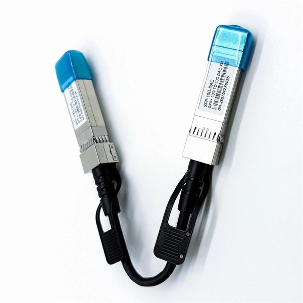
Which mode to choose for fused fiber optic pigtails
Fiber Type Choose single-mode for long-distance transmission and multimode for shorter runs. Connector Compatibility Match the connector (LC, SC, ST, etc. Fiber Count Select based on network scale—higher. Executive Summary: A fiber optic pigtail is one of the most commonly specified yet least understood components in structured cabling. Get the wrong connector type, the wrong polish, or skip proper fusion splicing technique—and you're looking at elevated signal loss, increased back reflection, and a. Fiber optic pigtails come with different connectors depending on your equipment: 3. Based on Fiber Count From your provided page, common options include: Higher fiber counts are ideal for data centers and high-density installations. You plug it into a switch, router, or patch panel. Protection Pigtail: Usually has a 0. Fiber optic pigtails are used to terminated fiber optic cables via fusion splicing or mechanical splicing as shown in the picture.
[PDF Version]
-
Calculation of Fiber Optic Patch Cord Splice Points
This calculator keeps optics, glass travel, and active forwarding separate so you can see where distance and delay enter the link. A fiber optic pigtail is a short length of optical fiber cable with a factory-terminated connector on one end and a bare, exposed fiber on the other. Unlike a patch cord—which has connectors on both ends—the bare fiber end of a pigtail is designed to be permanently spliced (either by fusion or. Estimate one-way and round-trip timing for fiber runs, optics, and active hops in home labs and backbone links. Direct point-to-point links with OS2 single-mode 1310 nm typically use 10 km+ of practical reach. 2 * Rear cable entries accommodate cables with diameter below 10mm. Splice loss depends on workmanship, fiber type, and method. Enter values based on recent OTDR traces, contractor QA records, or manufacturer. bers to be terminated from cable to cable or from cable to pigtail assemblies.
[PDF Version]
-
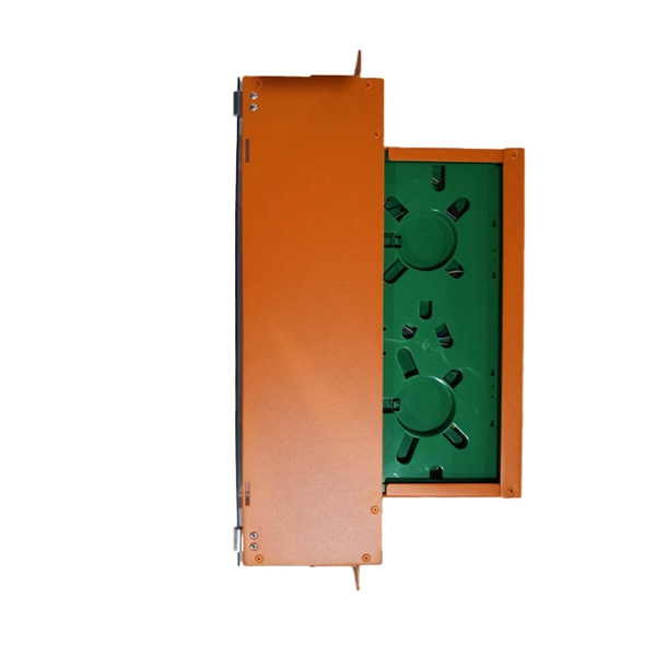
Fiber Optic Cable Splice Temperature Requirements
This Installation Manual suits for the Fiber Optic Splice Closure (Hereafter abbreviated as FOSC), as the guidance of proper installation. The scope of application is: aerial, underground, wall-mounting, duct-mounting and handhole-mounting. The ambient temperature ranges from –40°C. Fiber splicing is unavoidable in real-world deployments. Cables must be joined due to route length limitations, branching requirements, repairs after damage, or network upgrades. The Fiber Optic Association, Inc. (FOA) was founded in 1995 to help develop the workforce to build the fiber optic networks to support a rapid expansion in communications and the Internet. NEIS® are intended to be referenced in contrac documents for electrical construction ation or liability to users of this publication.
[PDF Version]
-
What to do if the fiber optic cable splice loss is too high
If high loss persists, inspect the splicer's alignment system. Clean the V-grooves and objective lenses with appropriate cleaning sticks and isopropyl alcohol. Dirt or dust on the fibre ends is one of the most common causes of high splice loss. Fusion splicers have settings that must be tailored to your fibre type and condition. Modern fiber optic networks usually keep splice loss low, as shown below: You should know that each splice can add 0. Understanding its causes and solutions is critical for reliable fiber optic installations. Poor Fiber Cleave: Angled or chipped cleaves prevent proper. Neglecting minor problems can lead to higher splice losses, increased signal attenuation, and long-term damage to fibre networks. This. One problem I continue to see is unexpected high loss during spicing between exchange-to-exchange network, particularly in the feeder and backbone segments, which can seriously impact the performance of the PON networks.
[PDF Version]
-
Huawei Switch Industrial Mode Settings
This document describes how to set the system parameters on s series switches. Below are the tasks that are performed in this document. View Logs: To stop viewing logs in real-time (i. The method for starting and stopping viewing logs on a Huawei backbone switch. Specify the following commands to assign a port to VLAN 10 in access mode. Use commands like display interface Gigabitethernet0/0/1 to verify correct configuration. For more service configurations, see the Switch Configuration Guide. It covers both static and dynamic routing commands, access control list configurations, and NAT settings. Configuring a Huawei switch isn't just about plugging in cables and ticking boxes—it's about building a network that's resilient, efficient, and ready to grow.
[PDF Version]
-
Switch Ethernet to Fiber Optic Port Mode
In this article, we'll explain how to connect multiple Ethernet switches using fiber optic cables and the equipment required for this to work. Network topology refers to the way in which the links and nodes of a network are arranged in relation to each other. The TC3212 10/100Base-T Ethernet Fiber Optic Converter is specifically designed for long distances and can extend LAN segments up to 80 kilometers and maximize bi-directional, fiber optic cable usage. It provides a 100Base-FX port that combines Ethernet Switching with the benefits of fiber optic. VERSITRON manufactures a wide range of fiber optic switches that provide links for your 10Base, 100Base, 1000Base Gigabit, and 10 Gigabit networks simultaneously. In real networks such as campuses, factories, metro POPs converters let you reuse existing switches and still run fiber for long distance, EMI immunity. Check each product page for other buying options. 5G, and gigabit options to expand your bandwidth. The SEL-2725 is an unmanaged five-port switch and copper-to-fiber-optic media converter. Single- or multimode fiber optics are available to accommodate a wide range of utility and industrial applications.
[PDF Version]
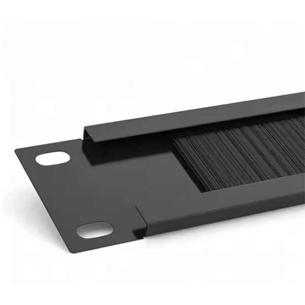
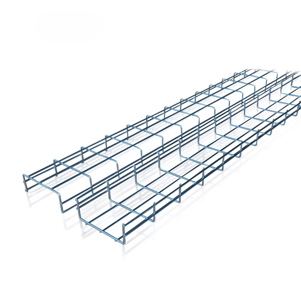
Telecom Racks & Cabinets
19-inch racks, wall-mount cabinets, open frames with high load capacity and seismic rating.
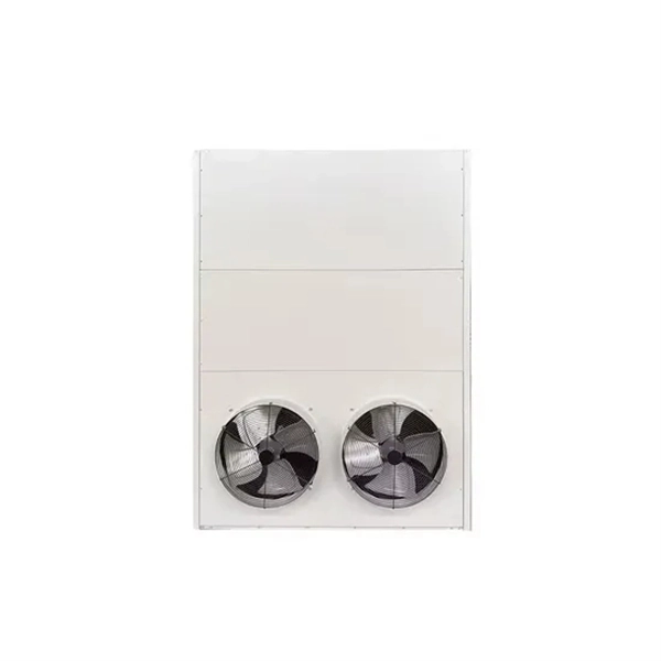
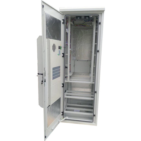
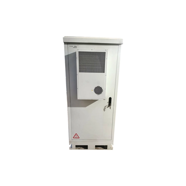
Outdoor Climate Cabinets
IP55/IP66 outdoor enclosures with integrated cooling/heating, -40°C to +55°C operation.
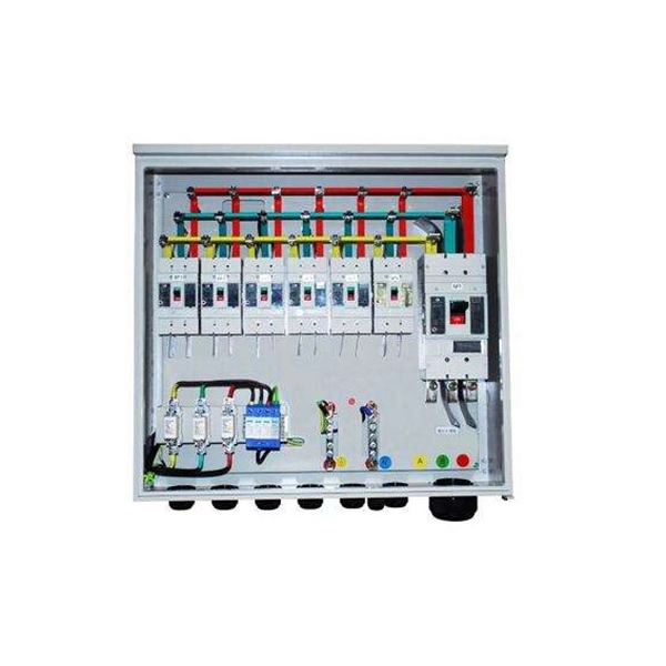
Smart PDUs & Power Distribution
Intelligent PDUs with remote monitoring, per-outlet switching, and environmental sensors.
Shelters & Network Cabinets
Prefabricated telecom shelters, emergency comms shelters, and network cabinets with cable management.