-
What type of copper busbar is used for low-voltage switches
ETP copper, known as C11000, is widely used for busbars due to its high conductivity and affordability. In power engineering, particularly within low-voltage switchgear and packaged substations, copper busbars are the vital conduits for energy transmission. Their precise specification directly impacts a system's safety, reliability, and economic viability. See how simple installation can be in distribution switchgear, marine transportation, machinery manufacturing, busduct and power generation. A busbar is a metal bar, usually made of copper or aluminum, that carries electricity inside switchgear. They are easy to install and offer a high surface area, which is great for heat dissipation. In most assemblies you will find horizontal main bars, vertical risers, neutral and equipment-ground buses, and purpose-designed.
[PDF Version]
-
How to calculate the copper busbar dimensions of a distribution box
The Busbar Size Calculator helps engineers and electricians find the right copper or aluminum busbar dimensions based on current capacity, material type, and environmental conditions. This article explains how the calculator works, the standards it follows (IEC and NEC), and what factors influence. Choose to calculate by Current (Amps) or Power (kW). Enter your system's parameters (e. Select the busbar Material (Copper or Aluminum). Certs, quotes, and scheduling all in one place. 1 Busbar current. This post covers all details you required to know about the bus bar sizing and how to use this professional calculation tools to ensure your systems meet IEC 61439 and NEC (NFPA 70) standards. Note = Ampacity based on typical DIN 43671 / IEC.
[PDF Version]
-
10kV Rectangular Busbar Current Carrying Capacity
Use this Busbar Rating Current Calculator to calculate the safe current-carrying capacity of copper and aluminum busbars using physical dimensions, material properties, ambient temperature, and mounting configuration. To calculate Busbar Current, enter the width (mm), thickness (mm), and material carry capacity factor (amps/mm^2). The electrical power system consists of many incoming & outgoing feeder connections, for which busbars are necessary. Busbars are critical components in electrical distribution networks, typically used to distribute high current among various circuits. Supports rectangular and round shapes. Excessive voltage drop can cause.
[PDF Version]
-
35kV busbar energized distance
333 (c) (3) requires a minimum distance of 10 feet (3. Why is it Important for Electrical Safety? It outlines the safe distance workers must maintain when. OSHA 29 CFR 1910. The first is clearance, or the distance through air between conductors of opposite polarity or between an energized conductor and ground. The distances are. For instance, OSHA's Table R-6 specifies minimum approach distances for various voltage ranges, ensuring workers adhere to safe practices when operating near live electrical parts. 5" away from the next closest bus bar and also separated via a sheet of 1/4" thick Garolite. 269 and 29 CFR Part 1926, Subpart V, as follows: The calculator provides the minimum approach distance, in feet or meters (depending on your. This article is for manufacturing, testing of non-segregated Bus Bars and Bus Ducts rated 600 V to 35 kV as per international standard ANSI C37. 23, Bus Bars and Bus Ducts Ratings, Bus Bar Supports, Bus Bars.
[PDF Version]
-
High-voltage tubular busbar in Democratic Republic of Congo
The Inga–Shaba EHVDC Intertie (officially: The Inga–Shaba Extra High Voltage D. Intertie; nickname: Inga–Shaba and also referred to as Inga–Kolwezi) is a 1,700 kilometres (1,100 mi)-long high-voltage direct current overhead electric power transmission line in the Democratic. To connect various high voltage (HV) components to the HV system, TE also delivers a wide variety of busbars. In cooperation with the customer, these can also feature TE's Bus Bar Insulation Tubing (BBIT). Busbars provide a safe HV connection on shorter distances. We offer Copper and Aluminium Tubular Busbars in a range of sizes, as well as the accessories to suit 33kV, 66kV and 132kV substations. Our in house technical support team can offer interpretation of substation drawings and. Chalco is a leading manufacturer of tubular aluminum busbars, offering high-conductivity and corrosion-resistant solutions made from alloys such as 6061, 6063, 6101, 1350, 1370, 1060, and 1070.
[PDF Version]
-
Does the 17 ring main unit have a small busbar
The unit links incoming and outgoing feeders through a busbar, which allows sections of the network to be switched off safely for maintenance without cutting off the entire system. Without them, this system cannot operate. RMUs help control power flow, isolate faulty sections, and protect equipment. They ensure reliability in medium voltage networks. This article explains the components of Ring Main Unit. A Ring Main Unit (RMU) is a factory-assembled, metal-enclosed switchgear device designed specifically for medium-voltage electrical distribution networks operating in a ring or loop configuration. According to IEC 62271-200 standards, RMUs serve as load connection points in ring-type distribution. Figure 1 – Typical ring main unit. Here, we provide an overview of common substation busbar configurations—Single Bus, Main and Transfer, Double Breaker/Double Bus, Ring Bus/Ring Main, and Breaker and a Half.
[PDF Version]
-
Price of 35kV busbar protection box in Serbia
We are Busbar manufacture and supplier, provide Customized 10kv35kv Busbar Connector Protection Box I/T/L Insulation Protection Box on sale,factory price. Bus boot is flexible electrical insulating boot / shroud for busbar and switchgear connections upto 36KV. Made from specially formulated Polyvinyl Chloride (PVC) material to provide excellent electrical insulation and to. Made of radiation cross-linked polyolefin material, with excellent physical and chemical electrical properties, it is the insulation treatment material for busbar connection, also suitable for 1KV/10KV/35KV voltage level, with "I" "T" "L " and other shapes of protective boxes. Technical Properties Type of Sample Red;"X" type;100×10 double busbars lapping with 100×10 double busbars. This product does not deform or shrink under heat. It boasts uniform wall. Material: Radiation-crosslinked modified polyolefin Shrink ratio: 2.
[PDF Version]
-
How long should a 10kV busbar be grounded
5 Grounding bus bars shall be 1/4” x 2” or 4” in cross section by 24” long with standoff insulators. For systems with 110kV and above, where the neutral point is effectively grounded, the metal sheath of single-core cables should be directly connected to the substation grounding device through a grounding switch. The grounding electrode conductor connection to. At the heart of a good grounding scheme is the ground bus bar: a solid, low-impedance conductor that ties all equipment grounding conductors (EGCs) together and connects them to the grounding electrode system. Rather than leaving stray green or bare wires looping around a panel, a ground bus bar. In 10kV power distribution systems, the proper setup of an earthing switch (or grounding switch) is critical. It's essential for safe equipment maintenance. A well-designed layout boosts electrical reliability, ensures mechanical stability, and helps extend system life.
[PDF Version]
-
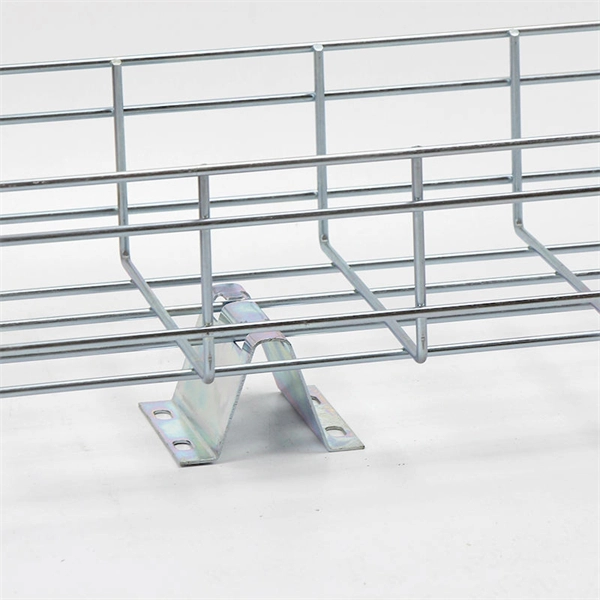
Bus trunking and busbar trays
This comprehensive guide compares busbar trunking systems to traditional cable setups, explores the topic of contactor coil voltage (AC vs DC), and helps professionals determine the right choice for their applications. Circuits can be added and removed easily as they are located just above their respective racks. This allows you to make. Busbar systems offer a modern, efficient alternative. EAE Electric started the production and use of busbar trunking.
[PDF Version]
-
Calculation of Low-voltage Busbar Bronze Plate
Busbar voltage drop is calculated using Vd = I x Z x L, where I is the current, Z is the impedance per unit length (R + jX), and L is the busbar length. For a rectangular copper busbar, DC resistance per metre is R = rho / (width x thickness) in micro-ohms/m. The busbar sizing calculator determines the required busbar dimensions based on the continuous current rating, short circuit withstand, and thermal limits for switchgear assemblies. The current rating is calculated from the conductor cross-sectional area, material (copper or aluminium), and maximum. Busbar calculation/selection is done in two ways: Built for electricians, apprentices, and electrical engineers who want faster practice and better exam prep. The IEC 61439. You may come across “Busbar Down for Maintenance” warning signs somewhere. This leads to brittle insulation and eventually.
[PDF Version]
-
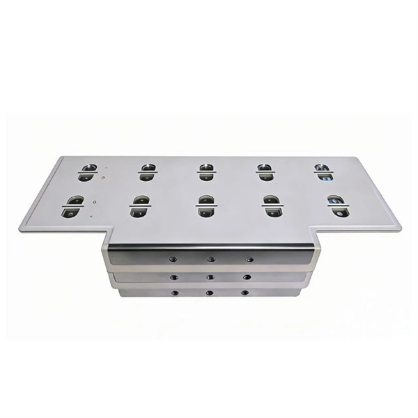
Installation method of small busbar at the top of the cabinet
Mount the brackets inside the cabinet first. Tighten all bolts to the specific torque settings. You can use heat-shrink tubing or insulation covers to keep the bars. By the end, you'll have a solid grasp of busbar processing intricacies, from material inspection to final installation, ensuring optimal performance and safety in electrical applications. Its primary function is to distribute power from incoming feeders to outgoing feeders. Method gives details of how the work will be carried out and how related. Do you have a question about the SIS BUS BAR SYSTEMS and is the answer not in the manual? Page 1 INSTALLATION INSTRUCTIONS SIS BUS BAR SYSTEMS GERMANY HAMBURG • WIRGES • KIRCHAICH • DRESDEN AUSTRIA MARCHTRENK | HUNGARY KECSKEMÉT | CHINA SHANGHAI | USA HARTWELL. Page 2 Internet:. It has three separate bars for the different phases of power. It does not expand too much when it. This methodology document uploaded by HSE Documents for installing power-electrical bus bars is a crucial aspect of electrical systems, ensuring efficient power distribution across various components.
[PDF Version]
-
The busbar is included inside the distribution cabinet
Inside every professionally built distribution cabinet, the neatly aligned busbars form the structural backbone of electrical energy transmission. These busbar conductors carry large currents and serve as critical links between transformers, switching devices, and downstream loads. Like blood vessels in the human body, it closely connects various electrical components in the distribution cabinet to achieve efficient transmission and distribution of. Busbar System: The Core Power Distribution Path The busbar system is the central component of any switchgear cabinet. Busbars are typically made from copper or aluminum due to their. Decades of field data—covering hundreds of thousands of low-voltage switchgear and power distribution cabinet installations—confirm: These designs are validated through: Temperature rise testing consistently shows that optimized, non-full-overlap joints meet or exceed international requirements. 5% annually through 2032, an increase that's driven by several key factors. 3/4/5 conductors available.
[PDF Version]
-
What to do if there is a 35kV busbar fault
This article introduces a case of 35kV ring main unit busbar insulation breakdown failure, analyzes the failure causes and proposes solutions, providing reference for the construction and operation of new energy power stations. 1 Accident Overview On March 17, 2023, a photovoltaic. Busbar faults in transmission and distribution networks can arise from various issues: Mechanical failures from physical stress or improper installation. These faults can lead to significant equipment damage, extended power outages, and severe safety hazards, underscoring the importance of robust. High short-circuit power levels at the busbar location can cause catastrophic damage if the fault is not cleared immediately. Minimizing the duration of the fault current limits the thermal and mechanical stresses placed on the system. What are the different types of busbar protection schemes? Busbar protection schemes can be categorized into: Differential. A busbar protection must be capable of clearing all phase-to-earth faults, and in the case where they can occur, phase-to-phase faults. Policy regarding fault clearance times required from busbar protection varies from utility to utility.
[PDF Version]
-
How to connect a small AC busbar
It is usually necessary to joint busbars on site during installation and this is most easily accomplished by bolting bars together or by welding. For long and reliable service, joints need to be carefully made with controlled torque applied to correctly sized bolts. Whether you're a seasoned professional or an enthusiastic. No description has been added to this video. I also have a subpanel in my garage. Inside my main (service) panel, I see the. This article aims to shed light on the importance of proper busbar connections, the different materials used in busbars, the types of busbars, the techniques employed for their connections, and their current carrying capacity. 2 How are bus bars connected? 3. You'll discover the essential tools and techniques.
[PDF Version]
-
How to connect the internal small busbar of the central power switch cabinet
This guide will walk you through every step of the process, from selecting the right materials to securing connections and ensuring safety. Bus bars play a crucial role in electrical distribution systems by providing a reliable and efficient way to conduct electricity within electrical panels. Whether you're a seasoned professional or an enthusiastic DIYer, our detailed instructions will equip you with the knowledge and confidence to tackle this. This wiring diagram tutorial will help you understand the connections in a distribution board for efficient electrical setup. Welcome to my channel! In this video, I am going to show 3 phase panel board internal bus bar connection diagram. The busbar shims and hardware bag in the cubicle packaging. Remove the protection plates in front of the bars to allow access to the.
[PDF Version]
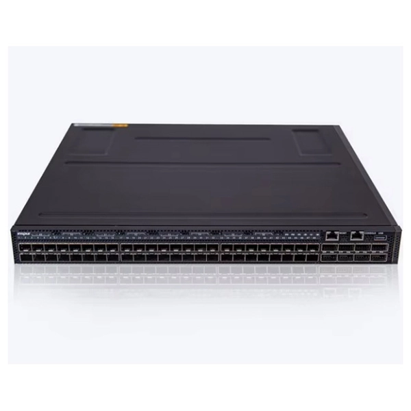
Telecom Racks & Cabinets
19-inch racks, wall-mount cabinets, open frames with high load capacity and seismic rating.
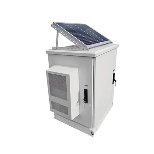
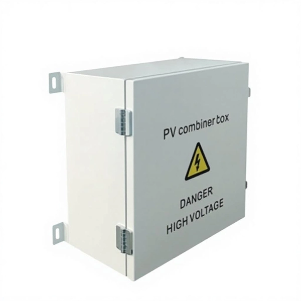
Outdoor Climate Cabinets
IP55/IP66 outdoor enclosures with integrated cooling/heating, -40°C to +55°C operation.
Smart PDUs & Power Distribution
Intelligent PDUs with remote monitoring, per-outlet switching, and environmental sensors.
Shelters & Network Cabinets
Prefabricated telecom shelters, emergency comms shelters, and network cabinets with cable management.