-
Can wire mesh cable trays be welded in Morocco
List of suppliers for Welded mesh Morocco. Request for quotes, good deals, exporters. Wire Mesh Cable Tray is a made from versatile material that offers numerous benefits across a wide range of applications. Stainless steel welded wire mesh is corrosion resistant & uniform in appearance. Welded wire mesh cable trays are open-grid support systems engineered from high-strength steel wires—Q235B carbon steel (mechanically equivalent to ASTM A36) or 304/316 stainless steel—precision-welded into 50×100mm (~2×4") or 100×200mm (~4×8") grids with >90% open area. The reason for our rise towards the pinnacle of success is the characteristics of our range such as durability, reliability and corrosion resistance, which has earned us. s and illustrations without notice. All illustrations, descrip-tions and technical information included in this document are provided as indica-tions and cannot be held against Legrand. Not all cable trays are equivalent.
[PDF Version]
-

Which companies in South Africa manufacture wire mesh cable trays
Saar Industries is a leading wire mesh cable tray manufacturer in South Africa, offering durable, corrosion-resistant, and easy-to-install cable solutions for industries. In 2014, our business expanded into manufacturing, allowing us to gain full. SAAR Industry is trusted Wire Mesh Cable Tray manufacturers in South Africa, suppliers and exporters in South Africa, we pride ourselves as being an ISO 9OO1-2O15 certified company, and therefore all our products are subject to high standards with 6+ Years experience and international manufacturing. Cable trays, welded mesh, poultry cages & trolleys in electro-galv, pre-galv, powder-coat or plain—served from Electron, Johannesburg to Africa and beyond. Please note (SG) finish on all Welded Wire Mesh products is. Our welded mesh cable trays are made from high-quality welded steel or stainless-steel. Providing a strong and durable solution for effective and efficient routing and support for cables and conduits. This product is designed to meet the requirements of all relevant cable and data installations, whether you need to run cables horizontally, vertically, or.
[PDF Version]
-
How to install a wire mesh cable tray machine
Whether you're working on an industrial, commercial, or data center project, this step-by-step guide will help you get it done safely and efficiently. 🔧 What You'll Learn: Preparing the installation area and measuring for accuracy Installing mounting brackets and ensuring proper. Wire mesh cable trays provide an excellent solution for managing and organizing cables efficiently. In this complete installation guide, we'll walk you through the process of installing wire mesh cable trays step-by-step, complete with images to illustrate each stage What is a Wire Mesh Cable Tray?In this video, we'll walk you through the entire process of installing a wire mesh cable tray system, from preparation to completion. 🔧 What You'll. For detailed information about the product, please visit our website: https://link. Qualified field personnel working to a. en completely installed, without damage either to conductors or structural system use maintain spacing or to keep cables in place when the tray is ect the minimum bend ra-dius for cables as they exit the bottom of the cable tray. A rung spacing of 6 to 9 inches (150 to 230 mm) is preferable when.
[PDF Version]
-
Requirements for welded partitions of mesh cable trays
Wire mesh shall be welded at all intersections. This section describes specific requirements, products, and methods of execution relating to cable management systems including tray, tray connectors, supports, brackets, engineered seismic bracing, vertical and/or horizontal offsets, grounding, and hardware for a complete system. ASTM A 123 - Zinc. maintain spacing or to keep cables in place when the tray is ect the minimum bend ra-dius for cables as they exit the bottom of the cable tray. A rung spacing of 6 to 9 inches (150 to 230 mm) is preferable when the cable tray cont d for instrumentation and control applications that require. Grounding is one of the most critical NEC considerations when installing metallic cable trays. The content is written to be SEO-friendly and compatible with Yoast SEO for WordPress. Introduction and. Welded wire mesh cable trays are open-grid support systems engineered from high-strength steel wires—Q235B carbon steel (mechanically equivalent to ASTM A36) or 304/316 stainless steel—precision-welded into 50×100mm (~2×4") or 100×200mm (~4×8") grids with >90% open area. ASTM A123 – Specification for Zinc (Hot.
[PDF Version]
-
Spacing between cable trays and cable tray connecting pieces
Support spacing for cable trays must align with the manufacturer's instructions, as outlined in NEC 392. Generally, standard trays require supports every 6 to 10 feet, while heavy-duty, long-span trays can handle distances of up to 20 feet between supports. The spacing between trays, whether horizontal or vertical, depends on various factors like cable type, environment, and tray material. Proper installation can significantly reduce electromagnetic interference, prevent fire hazards, and improve overall efficiency. The National Electrical Code is a set of principles designed to promote public safety and welfare, as well as safeguard public health by regulating the design and operation of electrical facilities and. Below are the key principles to guide the layout of E&I cable trays, focusing on practical, safety, and efficiency aspects.
[PDF Version]
-
Theoretical weight of long-span cable trays
This tool estimates tray self-weight from material density and an approximate metal volume. For solid and perforated trays, it treats the tray as a formed sheet: Developed sheet width per meter: Dev = W + 2H + 2R Metal volume per meter: V = Dev × t × 1 × (1 − Open%). Estimate cable tray self weight quickly for planning and procurement accurately. Export results instantly for schedules, submittals, and field checks. Density values are typical engineering references. Ladder cable tray is available in widths of 6, 9, 12, 18, 24, 30, 36, 42 and 48 inches with rung spacings of 6, 9, 12 or 18 inches. Note that wider rung spacings and wider cable tray widths decrease the overall strength of the cable tray. A rung spacing of 6 to 9 inches (150 to 230 mm) is preferable when the cable tray cont d for instrumentation and control applications that require additional protec eferred to support and protect numerous small. Proper cable tray load calculation is essential for ensuring the safety and reliability of electrical installations. Our cable tray load calculator.
[PDF Version]
-
Reasons for the routing of cables in cable trays
Effective cable routing ensures that cables are installed in a manner that minimizes interference and maximizes efficiency. In industrial settings, electrical and instrumentation (E&I) cable trays or bridge racks play a critical role in organizing and supporting power, control, and signal cables across facilities. This article explains the main requirements and good practices for cable tray systems, including tray types. A cable tray layout is a crucial aspect of electrical system design that dictates how cables are managed, organized, and protected within a facility or building. Cable trays give cables a clear path. Provide adequate air circulation.
[PDF Version]
-
How to run large cables overhead without using cable trays
A raised floor system is a raised access floor that allows for cables and wiring to be run beneath the floor, making it easier to run power and data cables throughout an open space, without the need for installation in the ceilings or other hard to reach areas. Whether suspended from the ceiling, wall-mounted, or supported by racks and cabinets, overhead cable management systems are flexible and scalable. They can easily be moved, reconfigured, or expanded as needed to meet changing requirements and evolving connectivity needs. Overhead cable management. The world's only hand-bendable cable tray that requires no labor-intensive cutting and clipping in order to construct fast cable tray bends installs overhead, on walls and under access floors. They are often installed on ceilings or walls. If a cable must cross a walkway, plan for protection rather than just leaving it exposed.
[PDF Version]
-
Indoor cable trays installed along the wall
This guide provides step-by-step instructions on installing a cable tray on a wall, covering different types of cable trays, tools needed, and safety tips. In this case, hiding your cables by installing the cables inside the walls is the better option as this will completely hide them from view and unintentional tampering. The guide includes diagrams for mounting cable trays on walls using pre-fabricated flanges or channels, laying cables, and selecting the. This guide covers the critical steps, from selecting the right electrical cable tray and performing accurate cable fill calculations to managing a safe cable pull through and ensuring all bonding and grounding requirements are met. Our knowledgeable production team works closely with each customer to provide quality solutions based on your schedule and budget. The following pages address the 2014 National Electrical Code® requirements for cable tray systems as well as design solutions from practical experience. The information has been organized for.
[PDF Version]
-
Latest Regulations for Fire Cable Trays
The use and installation of cable trays is covered by legally enforceable OSHA regulations in 29 CFR 1910. Scope: Firestopping for busway, cable trays, cables, and trunking passing through walls in enclosed electrical installations. Where cables pass through shafts, walls, slabs, or enter electrical panels or cabinets, openings shall be tightly sealed with firestopping materials in accordance with. The primary rulebook used in the safe use of cable trays is NEC Article 392. In addition, this document contains several references to provisions of the National Electric Code. Article 728 of the 2017 National Electrical Code (NEC) governs the installation of fire‑resistive cable systems used to ensure survivability of critical circuits for a specified time under fire conditions. This post gives you a field‑ready checklist with practical notes and AHJ expectations.
[PDF Version]
-
How to calculate the quantity of iron components in cable trays
The calculator supports multiple tray sizes (100-600mm), various cable types, and provides detailed formulas for fill ratio, weight estimation, and structural analysis. Tip: Standard mesh configurations are 25×50mm or 50×50mm. Smaller mesh provides better support for smaller. The primary rulebook used in the safe use of cable trays is NEC Article 392. This is a description of how to select, install, and support these metal or plastic frames, on which electrical wires are installed. You should consider it as a series of instructions that make the buildings resistant to. The right cable tray sizing calculator helps engineers turn cable schedules into a verified tray width and fill check before material ordering and site installation. This calculator features an interactive interface with advanced visualizations. Accurate fill ratio analysis and tray sizing per NEC, IEC 60364, and BS 7671 standards. Enter your cable schedule below to get started.
[PDF Version]
-
What are junction boxes cable trays and cable management systems
Understanding the types of cable containment systems, including trays, trunks, and conduits, helps engineers and contractors select the best solution for performance, safety, and compliance. Cable Load and Thermal Management 2. Thor specializes in R&D and overseas technical support for high-voltage cable junction boxes and other power distribution equipment. He's deeply familiar with electrical standards and application needs in Europe and North America. Efficient cable management is essential for maintaining organized, safe, and high-performing electrical systems in industrial, commercial, and residential settings. What Are Cable Management Systems? Cable management systems refer to a range of products and techniques designed to organise.
[PDF Version]
-
What specifications should be used for cable trays in the workshop
Only specific cable types are permitted to be installed in cable trays, as defined by applicable codes. Examples include: Power and lighting cables with tray ratings. When properly selected and installed, cable trays simplify routing, improve accessibility, and support future expansion while. In practice, cable tray dimensions are a system of interrelated measurements —width, depth, length, and material thickness—that directly affect cable fill compliance, heat dissipation, structural loading, and long-term expandability. It has cables organized, cool, and off the ground. In the case of large undertakings, it is not only the low price that matters when selecting the appropriate system. However, any installation must adhere strictly to the National Electrical Code (NEC) standards.
[PDF Version]
-
Cable trays are laid under the bridge
Cable trays are a part of a planned cable management system to support, route, protect and provide a pathway for cable systems. Cable trays support cables across open spans in the same way that roadway bridges support traffic. Cable trays are used as an alternative to open wiring or electrical conduit systems, and are commonly used for cable management in commercial and industrial construction. They are especially useful in situations where changes to a wiring system are anticipated, since new cables can be installed by. Cable tray systems include ladders, troughs, channels, solid bottom trays, and other similar structures.
[PDF Version]
-
National Standard for Angle Iron Cable Trays
The primary rulebook used in the safe use of cable trays is NEC Article 392. This is a description of how to select, install, and support these metal or plastic frames, on which electrical wires are installed. This standard specifies the requirements for nonmetallic cable trays and associated fittings designed for use in accordance with the rules of the Canadian Electrical Code (CEC) Part 1, and the National Electrical Code® (NEC). Covers construction and test requirements for. us-trations without notice. All illustrations, descriptions and technical information included in this document are provided as indications and can cable trays are equivalent. The flexibility and scalability of cable trays make them an ideal choice for environments where cable density and organization can. NEMA Standards Publication 1 (0$9 ( 6WDQGDUGIRU0HWDO&DEOH 7UD6VWHPV National Electrical Manufacturers Association NEMA Standards Publication VE 1-2017 CSA Group Publication CSA C22.
[PDF Version]
Telecom Racks & Cabinets
19-inch racks, wall-mount cabinets, open frames with high load capacity and seismic rating.
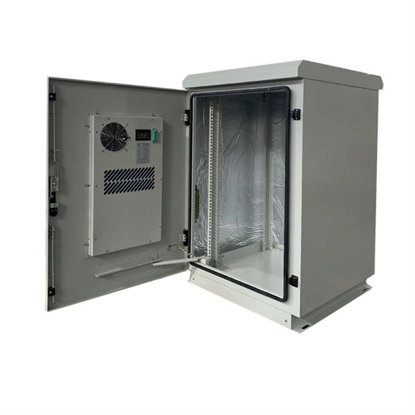
Outdoor Climate Cabinets
IP55/IP66 outdoor enclosures with integrated cooling/heating, -40°C to +55°C operation.
Smart PDUs & Power Distribution
Intelligent PDUs with remote monitoring, per-outlet switching, and environmental sensors.
Shelters & Network Cabinets
Prefabricated telecom shelters, emergency comms shelters, and network cabinets with cable management.