-
A Brief Analysis of the Development Trends of Optical Fiber Communication
Optical Fiber Communication (OFC) revolutionizes modern telecommunications, enabling rapid data transfer across long distances with minimal signal loss. This comprehensive review explores OFC's historical evolution, core principles, components, and versatile applications. Fiber Optics by Application (IT and Telecoms, Medical, Robotics, Others), by Types (Multi-Mode Fiber Optics, Single-Mode Fiber Optics), by North America (United States, Canada, Mexico), by South America (Brazil, Argentina, Rest of South America), by Europe (United Kingdom, Germany, France, Italy. Technological Innovations 1. Advancements in Ultra-High-Speed, Large-Capacity Transmission The deployment of 400G optical backbone networks has already reached commercial scale, while the development of next-generation 1. 6T backbone networks is underway. In this blog post, we will discuss fiber optics.
[PDF Version]
-
Experimental Process of Making Fiber Optic Patch Cords
Explore the complete manufacturing and testing process of fiber optic patch cords, including polishing, assembly, and IL/RL testing. Discover how Gcabling ensures consistent quality for high-performance connectivity. Their performance directly impacts signal quality, insertion loss (IL), and return loss (RL). I once visited. A fiber patch cord and pigtail production line typically involves several key processes to ensure high-quality output. From cable cutting to connector assembly and testing, you will gain valuable insights into the production of. What is an Optical Fiber Patch Cord/Patch Cable? An optical Fiber Patch Cord, also known as a fiber jumper or patch cable, is a short section of fiber cable that is terminated with optical connectors on both ends.
[PDF Version]
-
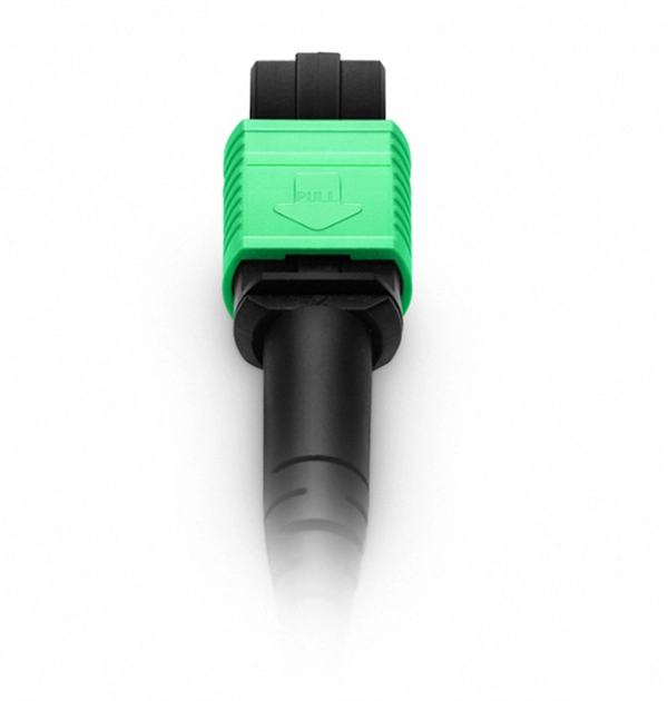
Optical fiber cable parallel connection line
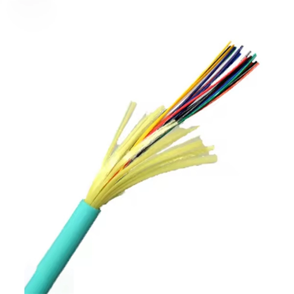
A parallel link is accomplished by combining two or more channels. Parallel optical links can be achieved by using eight fibers (4 fibers for Tx and 4 fibers for Rx), twenty fibers (10 fibers for Tx and 10 fibers for Rx) or twenty-four fibers (12 fibers for Tx and 12 fibers for. Parallel optic interfaces (POIs) are a fiber optic technology primarily targeted for short-reach multimode fiber systems (less than 300 meters) that operate at data rates greater than 16G. Parallel optic interfaces differ from traditional fiber-optic communication in that data is. As data rates have increased in response to more demanding applications, the market has gravitated to parallel optics. In this, we'll discuss parallel MMF cabling. When transceiver. MMF vs SMF: Multimode fiber (MMF) is typically used for short-distance, cost-efficient connections inside data centers and buildings, while single-mode fiber (SMF) is designed for long-distance, high-bandwidth transmission across campuses, metro links, and telecom networks. The right choice depends.
[PDF Version]
-
Effect Length of Optical Fiber Communication Technology
Fiber optic cable transmission distance is determined by two primary physical factors that affect signal quality as light travels through the fiber medium. The basic transmission mechanisms of the various types of optical fiber waveguide have been discussed in Chapter 2. The greater the distance, the greater. To meet demand of increase in the telecommunication data transmission. Total internal reflection (critical angle, using Snell's law). Lighter and thinner then copper wire. The cladding's refractive index is slightly smaller than that of the core, which confines light within the core and propagates by repeated total reflection at the boundary with the. An optical fiber, or optical fibre, is a flexible glass or plastic fiber that can transmit light from one end to the other.
[PDF Version]
-
Cable and Optical Fiber Survey Report
The report on the fiber optic cable market provides a holistic analysis, market size and forecast, trends, growth drivers, and challenges, as well as vendor analysis covering around 25 vendors. Fiber optic cables are needed for backhaul and fronthaul connectivity because they provide the required bandwidth for 5G base stations and small cell networks. Public cable companies lost 265,000 Internet customers in Q3 2024. 0 will significantly stem this trend. Where Are We Going? to telecom in the past five years (the majority to fiber). Disbursement occurs over multiple years. 19 billion by 2033, expanding at a CAGR of 10. Cable operators plan to carry out a growing number of network upgrades and new builds over the next 5 years, including FTTP-oriented, DAA-oriented, PON-oriented, DOCSIS-oriented, and. The UTC Fiber subcommittee serves as a platform for utility industry professionals and executives to address present and future challenges related to fiber optic networks. I need the full data tables, segment breakdown, and.
[PDF Version]
-
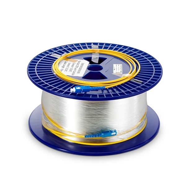
Inquiry about large-core diameter optical fiber G 652
652 fiber is typically 8-10 microns, with a cladding diameter of 125 microns. The difference in refractive index between the core and cladding allows the light signal to propagate within the core, thereby reducing signal loss. This document outlines the specifications for a single-mode optical fiber and cable designed for use around the 1310 nm zero-dispersion wavelength, suitable for both the 1310 nm and 1550 nm regions, and compatible with analogue and digital transmission. It details the fiber's geometrical, optical. Max. Ideal for cable mounting inside buildings, patchcords and/or i terconnection cables. It offers significant added value in Fibre-to-the-Home (F me splicing machines. A Fiber Reinfor ed Plastic (FRP) locates in the center of core as a non-metallic strength member.
[PDF Version]
-
Will the optical fiber distribution box have a BBU
It sits in an enclosure with the Battery Backup Unit (BBU) and associated wiring. It has an optical port connecting to the external Customer Splice Point, an Ethernet port connecting to the communications provider's (CP) router, and a telephony port connecting to the voice. units on towers, buildings, or light posts. The RRU is normally located at the top of a tower, roof, or similar bu lding object and very close to the antenna. On the other end, the. RRU and BBU are crucial components in base station construction, enabling a distributed architecture that improves efficiency and reliability. In a distributed base station. Fiber Optic Distribution Box (FDB) / Fiber access terminal box (FAT) / optical termination box (OTB) / Fiber termination box (FTB) / Optical Distribution box (ODB) are a compact fiber management box used for FTTH application. For more. The enclosure is attached to the wall with 2 screws, instead of the 4 on the previous ONT A template is provided with the unit to ensure correct screw location The enclosure will fit over a double back box to allow the connectorised cable to be inserted through the back of the unit.
[PDF Version]
-
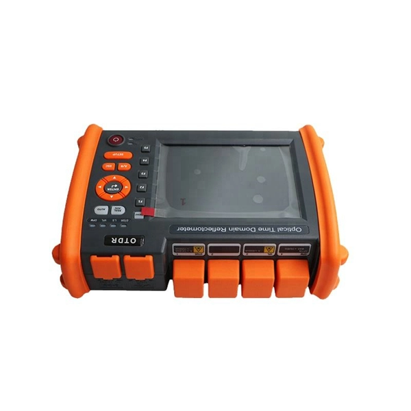
What dB value is considered acceptable for optical fiber splicing
Acceptable splice loss in optical fiber is typically considered to be less than 0. What is the typical acceptable splice loss for single-mode fiber using fusion splicing? What is the acceptable splice loss for multimode fiber using mechanical splicing? How does fiber alignment affect splice loss? Why is cleaning the fiber important before splicing? What role does the cleaver play. Acceptable dB loss for fiber depends on the component you're measuring: a single mated connector pair should lose no more than 0. 5 dB per kilometer depending on the type and wavelength. The total. However, acceptable values depend on: * Project specifications * Link budget calculation * Network type (FTTH vs backbone) * Customer SLA requirements 🛠 Fusion vs Mechanical Splicing * **Fusion splicing** typically gives lower loss (0. * **Mechanical splicing** usually results in. The splice loss is measured in decibels (dB) and is influenced by various factors such as the quality of the splice, the alignment of the fiber cores, and the type of splicing technique used. 5 dB, while for multimode. For each connector, we usually figure 0. However, various factors, such as fibre cleanliness, core.
[PDF Version]
-
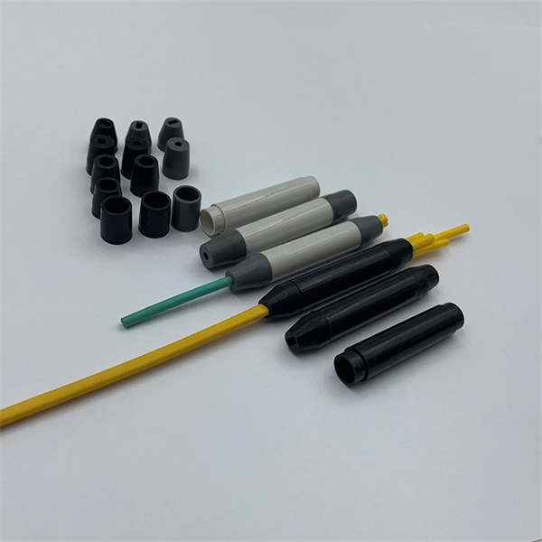
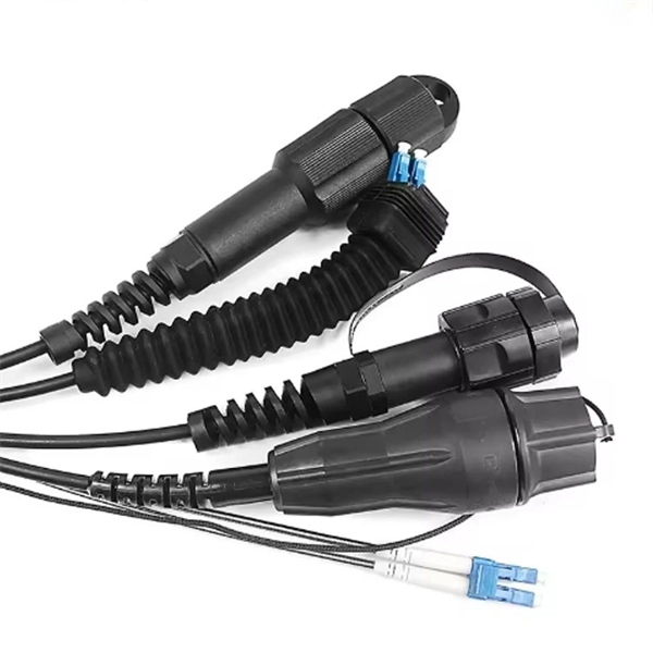
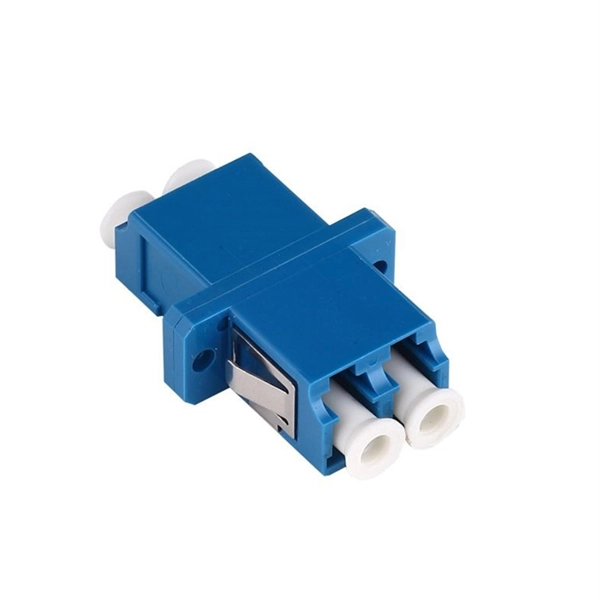
Is flexible optical fiber the same as a pigtail
When you build or upgrade a fiber network, the same four words pop up everywhere— fiber optic (bare fiber), pigtail, patch cord, optical cable. They're related, but they are not interchangeable. Mixing them up drives costs higher, increases loss, and slows your rollout. The good news? Once you nail. Executive Summary: A fiber optic pigtail is one of the most commonly specified yet least understood components in structured cabling. Get the wrong connector type, the wrong polish, or skip proper fusion splicing technique—and you're looking at elevated signal loss, increased back reflection, and a. Dual Connectors: Both ends are fitted with standardized connectors (e., LC, SC, ST), which may be identical (e. It is usually suitable for field termination using a mechanical or fusion splicer. But what exactly is a pigtail and why do you use it? In this article, we explain why they are important and which pigtail connector you should choose, with a focus on SC and LC pigtails. What is a pigtail? A pigtail is used to.
[PDF Version]
-
Acceptance Requirements for Optical Fiber Cable Splicing
IPC-A-640, officially titled “Acceptance Requirements for Optical Fiber, Optical Cable, and Hybrid Wiring Harness Assemblies,” provides acceptance criteria for cable and wire harness assemblies that incorporate optical fiber technology. The Contractor tasked to perform testing or splicing on any fiber optic cable will follow these testing standards to fulfill their contractual obligations. This testing. METR IBER MEDIA NET WORK Fiber Optic Cable Splicing, Testing and Acceptance Criteria for Contractors Version 1. Typical applications of these methods include aerial, buried, and underground splices. (2) American National Standard Institute/National Fire Protection Association (ANSI/NFPA) 70, 1993. d suppliers of electrical construction services. Unlike copper wire harnesses where a slightly imperfect crimp might still conduct electricity, a contaminated fiber end face or improper splice can completely block light transmission. The contractor submits test results. And then someone — usually someone who hasn't done this before — tries to figure out whether.
[PDF Version]
-
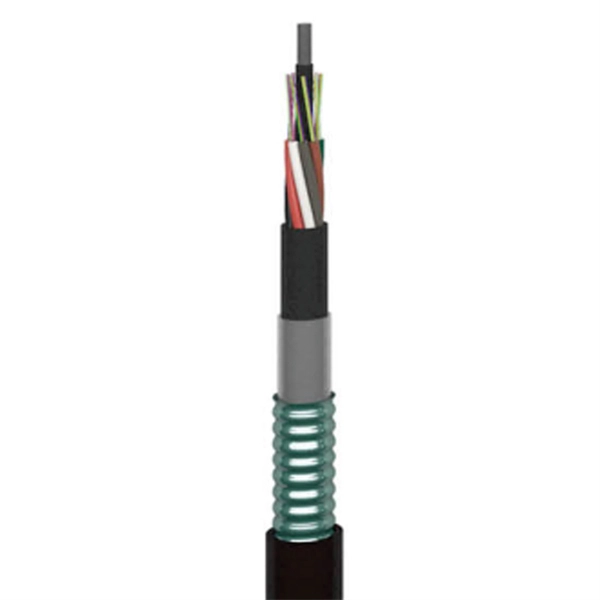
How much does 24-core optical fiber cable cost per meter
In practical terms, the current market range for a standard single-mode 24 core fiber optic cable typically falls between $1. For instance, a 24 core fibre optic cable price in Europe may differ from that in Southeast Asia due to transportation costs and regulatory requirements. These cables are available in both single-mode and multimode variants, each engineered for specific network requirements ranging from long-haul. Single-mode fiber (OS2): This is the industry workhorse. In 2025, the base glass price has stabilized. The price swing usually depends on the fiber count (e., 12-core vs 96-core) and brand. Commercial building installations with 100-200 network drops generally range from $15,000 to $30,000. Single-mode fibers (SMF) are typically used for long-distance. Knowing how much fiber optic cable costs, which factors can impact cost, and key cost considerations can help you avoid unnecessary expense and get the most out of your budget.
[PDF Version]
-
Optical cables are all based on the principle of optical fiber transmission
Fiber optic cables have revolutionized telecommunications, data transmission, and network infrastructure by offering a faster, more reliable means of communication. The core principles behind fiber optic transmission rely on optical technology, enabling the transfer of information. In this article, we will learn about Optical Fiber Light Transmission, Optical fiber light transmission is a technology that enables the transmission of data and information through thin strands of glass or plastic fibers using light signals. To. An optical fiber can be understood as a dielectric waveguide, which operates at optical frequencies. The device or a tube, if bent or if terminated to radiate energy, is called a waveguide, in general. fiber optics, the science of transmitting data, voice, and images by the passage of light through thin, transparent fibers.
[PDF Version]
-
How many kilometers of optical fiber cable are considered a backbone
Collectively, these fiber-optic systems stretch approximately 1. 5 million kilometre along the seabed, forming the backbone of global digital connectivity. As of early 2025, an estimated 570 active submarine cable systems span the world's oceans, with roughly 80 additional networks either under construction or in advanced planning stages. The Internet backbone is the principal data routes between large, strategically interconnected computer networks and core routers of the Internet. The fiber backbone carries enormous volumes of data. A total of 1,031 km of fiber optic cable has been installed across five routes: Arlit–Assamaka–Algerian border (220 km), Diffa–N'Guigmi–Chadian border (186 km), Zinder–Magaria–Nigerian border (117 km), Niamey–Dosso–Gaya–Benin border (300 km), and Niamey–Makalondi–Burkina Faso border (118 km).
[PDF Version]
-

How to connect the invisible fiber optic cable to the optical splitter
Connect the opposite end of the cable into the single end of the fiber optic cable splitter. When employing the first-level splitting method in a residential network, optical splitters offer flexibility for indoor or outdoor installation. Indoor options encompass locations like the community's central computer room, building's weak current well, or floor wiring box. more This video provides a step-by-step. This article will guide you through the necessary tools, materials, and methods on how to connect fiber optic cables effectively, ensuring you achieve optimal performance from your fiber optic network. Have a network installation project? Fiber Optic Cables: The primary medium for your connections. ① The connection environment should be dustproof, waterproof and shockproof.
[PDF Version]
-
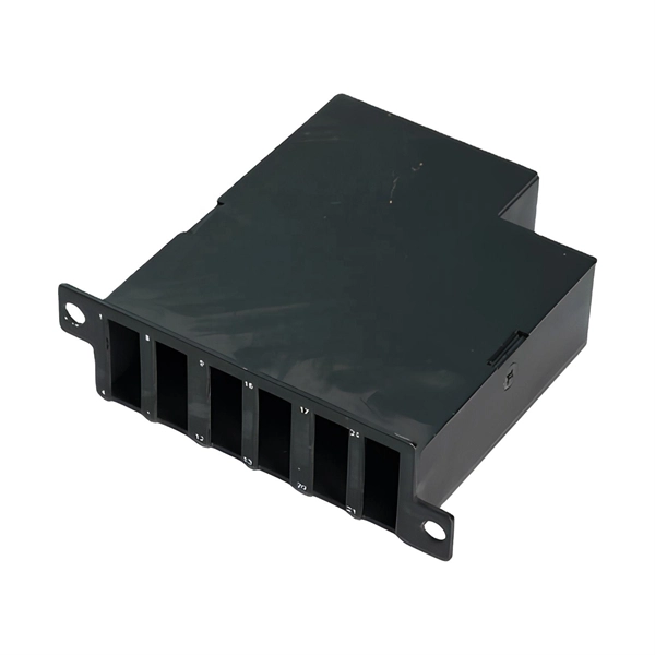
How to fix optical cables in a multi-frame fiber splicing tray
Learn how to splice fiber optic cable using fusion splicing with this complete step-by-step guide. Includes tools, best practices, loss standards (ITU-T G. 652), cost analysis, and FAQs for network engineers and installers. Adhering to precise methodologies, we can mend impaired cables. Fiber cable splicing is a critical step in building reliable fiber optic networks. Whether in data centers, telecom rooms, or outdoor FTTx deployments, proper splicing inside a fiber enclosure ensures low signal loss, long-term stability, and easy maintenance. Regardless of the type of fiber network you're deploying, be it for telecom, enterprise data centers, or smart city infrastructure, fusion splicing provides the benefits of. 🔧 Watch a real-time fiber optic splicing demo in action! In this step-by-step tutorial, learn how to splice fiber optic cables like a pro — perfect for telecom technicians, network engineers, and field techs. Whether you're installing a new network, expanding an existing one, or.
[PDF Version]
Telecom Racks & Cabinets
19-inch racks, wall-mount cabinets, open frames with high load capacity and seismic rating.
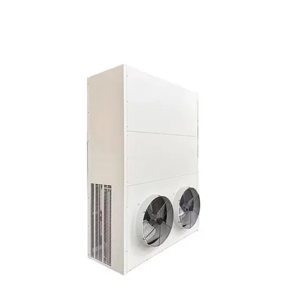
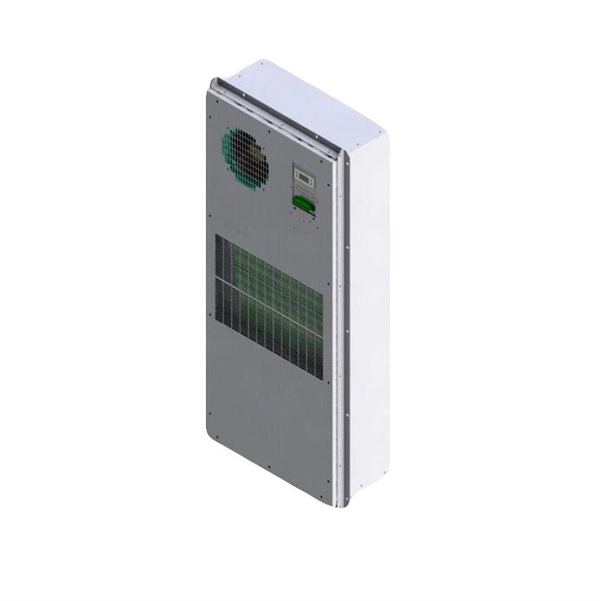
Outdoor Climate Cabinets
IP55/IP66 outdoor enclosures with integrated cooling/heating, -40°C to +55°C operation.
Smart PDUs & Power Distribution
Intelligent PDUs with remote monitoring, per-outlet switching, and environmental sensors.
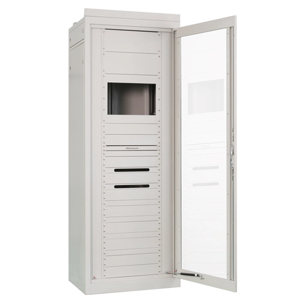
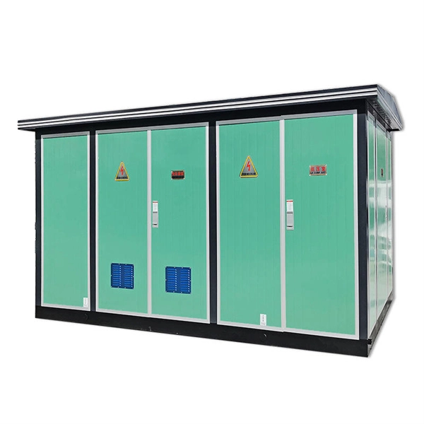
Shelters & Network Cabinets
Prefabricated telecom shelters, emergency comms shelters, and network cabinets with cable management.