-
Distribution Diagram of Fiber Optic Communication System
This template showcases a professional layout for Fiber-to-the-Home and Fiber-to-the-Building setups. It visualizes the connection between a central office and various end-user locations. By using light signals, fiber optics provide faster speeds and better reliability than. What to show on a network diagram? Fiber optic network diagrams represent the architecture and connectivity of fiber optic systems, and their design philosophy integrates technical, functional, and conceptual aspects. The diagrams abstract complex details of fiber optic systems to make them. Optical network system architecture provides a detailed overview of an optical communication system. It includes first determining the type of communication system (s) which will be carried over the network, the geographic layout (premises, campus, outside. PROVIDE SERVICE LOOP FOR ALL HORIZONTAL VOICE, DATA, AND VIDEO CABLES NOT TO EXCEED 10 FEET. LOCATION TO BE DETERMINED BY THE RUPM. PROVIDE (3) 30A SPARE CIRCUITS IN ELECTRIC PANEL. 3/4" AC FIRERATED PLYWOOD ON ALL WALLS, PAINTED WITH WHITE FIRE RETARDANT PAINT (DO NOT PAINT PLYWOOD LABEL).
[PDF Version]
-
Is fiber optic cable a communication medium
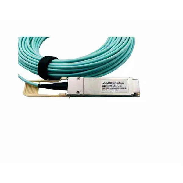
A fiber optic cable is a high-speed data transmission medium that carries information as light pulses through strands of glass or plastic fibers. The light is a form of carrier wave that is modulated to carry information. It forms the fundamental pathway through which information is transmitted, ensuring connectivity between networked devices. The selection of a. In a world driven by data, speed, and instant connectivity, fiber optic cables are the silent heroes powering everything—from your Netflix stream to global financial systems. These cables, thinner than a strand of human hair, carry terabytes of information at nearly the speed of light, transforming. This combination of this plus optical fiber (a high-performance transmission medium made of glass as thin as a human hair capable of trapping optical signals and transmitting them over long distances without significant attenuation) were game changers and set the stage for optical-based. Fiber optic cables are a transmission medium that transmits data or information through glass fibers, offering greater speed and bandwidth compared to traditional copper cable technology. What Is Fiber Optics Used For? The.
[PDF Version]
-
How can rain affect fiber optic communication
Weather conditions like heavy rain, snow, and extreme temperatures can cause physical damage to fiber-optic cables. Water and ice can seep into the cables, causing corrosion and degradation of the optical fibers. Fiber has glass strands, which are stronger than metal wires. Workers often put cables underground, and sometimes they use. Fiber optic internet, celebrated for its high bandwidth and reliability, is often touted as less susceptible to weather-related disruptions compared to legacy copper-based infrastructure like DSL or coaxial cable. How Weather Affects Fiber Internet Fiber-optic cables are usually buried underground, which protects them from many of the issues that traditional cable or. Rain can have a significant impact on the fiber optic cable installation process. Here are some of the ways that rain can affect the installation process: Safety risks: Rain can make the installation process more hazardous, particularly when working with electrical equipment.
[PDF Version]
-
New Fiber Optic Communication Technologies ofdm
Multi-carrier techniques such as OFDM (Orthogonal Frequency Division Multiplex) and DMT (Discrete Multitone) are already successfully applied in wireless and DSL (Digital Subscriber Line) systems. With the increasing need for data speeds and efficient use of bandwidth experts have been exploring the connection between OFDM, valued for. OFDM is a multicarrier modulation technique that divides the available bandwidth into multiple orthogonal subcarriers. Each subcarrier is modulated with a low-rate data stream, and the subcarriers are spaced at a minimum frequency separation that ensures orthogonality.
[PDF Version]
-
FC fiber optic interface communication is poor
Fiber polarity and connectors: Confirm correct transmit/receive pairs and connector types (LC, SC, FC). A swapped TX/RX or a mismatched connector can stop communication. Patch cables and patch panels: Replace suspected patch cables and test with a known-good fiber. This document describes how to troubleshoot fiber optic interfaces by addressing some of the fiber optic module and cabling specifications. There are no specific requirements for this document. This includes Doppler. Fiber Channel technology (Fibre Channel) is a network storage switching technology that can provide long-distance and high bandwidth, and can realize the transmission of large data files between storage, server and client nodes. Without the proper adapter, signals can degrade or become unstable, which can dramatically decrease the reliability of a network. This article outlines common problems with fiber optic media converters, along with practical solutions to support IT professionals and network administrators in effective troubleshooting and performance optimization.
[PDF Version]
-
Principles and Methods of Fiber Optic Communication in Smart Buildings
A practical, engineer-friendly guide to planning, installing, testing, and maintaining modern fiber optic networks for FTTH, FTTR, smart buildings, and data centers in 2026. A2 fiber and micro-duct blowing for future-proof FTTH / FTTR and campus. This is the FOA's Online Guide To Fiber Optics, Fiber Broadband & Premises Cabling. Plan around standards: TIA-568. Optical fiber communication systems have become the cornerstone of modern telecommunications over the past four decades. As the demand for high-speed, high-capacity data transmission continues to grow exponentially, these systems have become increasingly essential. Harnessing the power of light. Building | Telecommunications System Design: Telecommunications system design for buildings is a specialized project that integrates communication technology, spatial planning, and regulatory compliance, and is particularly crucial for residential complexes and building permit approvals. By harnessing fiber-forward technology, centralized intelligence through software-defined management, and innovative.
[PDF Version]
-
Block Diagram of a Digital Fiber Optic Communication System
TL;DR: A fiber optic communication block diagram visually breaks down how data travels through fiber optic cables—from signal generation to transmission, amplification, and reception. In this lecture, we are going to learn about Optical fiber communication, a Block diagram of optical fiber communication systems, types, and modes of optical fiber, and the advantages and applications of optical fiber communication. RECONSTRUCTION OF TEACHER EDUCATION IN SOMALIA: The Case of Garowe Teacher Ed. by Cambridge Early Learning Centre. There are mainly two types of optic cables are used - 1. Multi-Mode Optical Fiber Cable 2.
[PDF Version]
-
Long-distance fiber optic communication refers to
Long-haul transmission uses fiber optic cables to send data quickly and securely over long distances, connecting cities and countries for fast communication. Vision: Journal of Biomedical Research & Environmental Sciences main aim is to enhance the importance of science and technology to the scientific community and also to provide an equal opportunity to seek and share ideas to all our researchers and scientists without any barriers to develop their. Fiber Optics or Optical Fiber is a technology that transmits data as a light pulse along a glass or plastic fiber. The fiber which is used for optical communication is waveguides made of. DWDM technology allows multiple optical carrier signals (each on a different wavelength/laser color) to be transmitted simultaneously on the same fiber. Think of it as turning a single-lane road into a massive, multi-lane super-highway.
[PDF Version]
-
What are the setup methods for fiber optic communication
The process involves a combination of national infrastructure, local engineering, and property-level setup. In this guide, we'll break down the fiber installation process from start to. Fiber internet installation delivers the high-speed connectivity modern businesses need for video conferencing, cloud applications, and data-intensive operations. This guide breaks down the process in easy steps so you know what to expect. Aerial Service Drop: A cable coming from a pole to your house, connected at a small box called an. The Professional Association Of Fiber Optics www. org The Fiber Optic Association, Inc.
[PDF Version]
-
The Function of Fiber Optic Communication Shields
Shielded cables include an additional conductive layer—either foil (FTP), braid (STP), or both (S/FTP)—wrapped around the twisted pairs. This layer serves as a barrier against external noise like EMI and RFI, common in high-voltage, industrial, and medical environments. These platforms integrate advanced avionics, radar systems, data links, and communication networks that must function seamlessly in hostile, high-frequency environments. In these mission-critical contexts, electromagnetic interference (EMI) poses a silent but serious threat that can degrade signal. Basic Structure of Cable Shielding. A typical shielded cable, from the inside out, has the following structure: • Conductor Core: The core (copper or aluminum) that transmits current or signals; • Insulation: Insulates the conductor from the outside, preventing leakage; • Shield: The conductive. Foil Shielded Twisted Pair (F/UTP): All twisted pairs are foil-shielded and offer essential EMI protection, making them an affordable choice for moderately noisy environments. That's where armored and non-armored fiber cables come in.
[PDF Version]
-
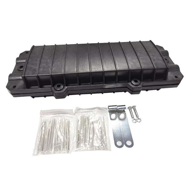
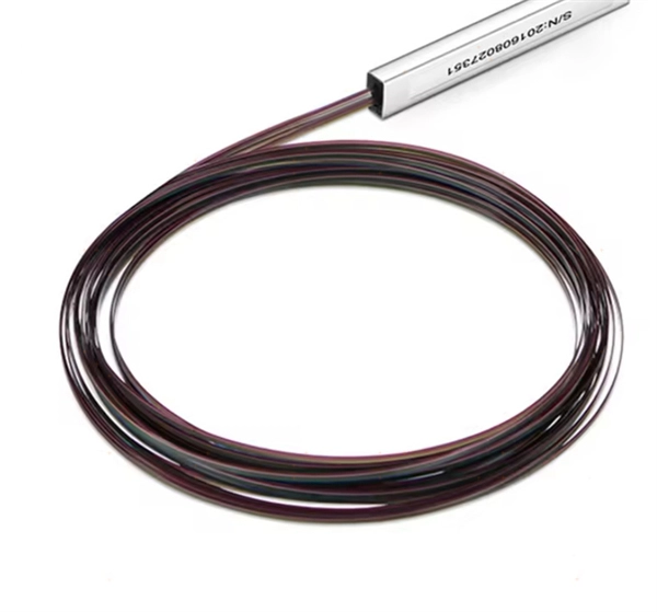
Core of Fiber Optic Communication Systems
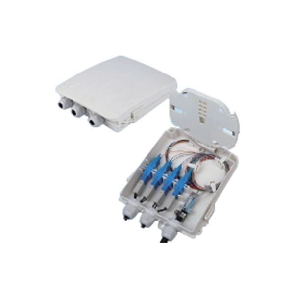
A fiber optic communication system uses thin strands of glass or plastic, called optical fibers, to transmit data as pulses of light. It's the backbone of the internet, telephone networks, and more, offering unmatched bandwidth and distance. It allows for. As a leading manufacturer of FTTH and CATV solutions, Junpu provides reliable optical communication components from cables to splice closures.
[PDF Version]
-

Demonstration Experiment of Fiber Optic Communication
How Fiber Transmits Signals By Light (Grades K-12) This is a demonstration of how communications signals travel as pulses of light over fiber optics, creating a fiber optic telegraph that sends signals as light and can send Morse code. Morse code was the signalling system used by the original. This document summarizes 10 experiments on optical fiber communication: 1. Studying a 650mm fiber optic analog link and the relationship between input and received signals. Key experiments include amplitude modulation, frequency modulation, and pulse width modulation, aimed at understanding fiber optic systems. An optical fiber is a glass or plastic fiber designed to guide light along its length, widely used in fiber-optic communication, which permits transmission over longer distances and at higher data rates than other forms of communications. As the photo below by AT&T from the 1970s showed, one hair-thin fibre can carry more signals than the giant copper telephone cable in the photo.
[PDF Version]
-
33 How to thread fiber optic cable through a communication conduit
Secure cables in trays or conduit and fasten with hook-and-loop ties to prevent compression. Installing fiber optic cable in conduit protects the cable from physical damage, moisture, and rodents while allowing future cable replacement or upgrades. Proper conduit installation requires attention to pulling tension limits, bend radius requirements, lubricant selection, and innerduct. Fiber optic cable transmits data as light pulses through thin strands of glass or plastic, offering high speed and bandwidth. The hair-thin glass cores within the cable are highly sensitive to physical stress and tight bending, which can cause signal loss or permanent damage. Outdoor cable may be direct buried, pulled or blown into conduit or innerduct, or installed aerially between poles.
[PDF Version]
-
Mobile Fiber Optic Communication Maintenance
This working paper explores the current trends in the maintenance of fiber optic networks, which are critical to supporting the high-speed, high-capacity demands of modern communication systems. Our highly-skilled team of professionals specialize in the installation, termination, splicing, and testing of fiber optics technology in virtually every possible environment, including permitting services and challenging right-of-way deployments. Key areas of focus include innovative maintenance techniques, predictive maintenance through AI and. Connect with local fiber optics experts now for seamless installation and future-ready connectivity.
[PDF Version]
-
What is fiber optic communication distortion
As pulses of light travel down a fiber optic cable, they can get stretched, distorted, and blurred. Optical fiber technology is essential for modern data transmission, operating through the movement of light pulses. This phenomenon can cause signals to overlap and degrade, impacting communication systems by. What is Distortion in Optical Fiber? Distortion in optical fiber refers to the degradation of the signal as it travels through the fiber, causing the signal to broaden and potentially overlap with adjacent signals, leading to errors in data transmission. Let a system has input signal and output signal. What is the condition for. • Why & to what degree do optical signals get distorted as they propagate down a fiber? • Signal attenuation (fiber loss) largely determines the maximum repeaterless separation between optical transmitter & receiver. This phenomenon, known as fiber optic dispersion, is a fundamental challenge that network engineers must overcome to achieve faster speeds and greater distances. Think of it like a group of runners.
[PDF Version]
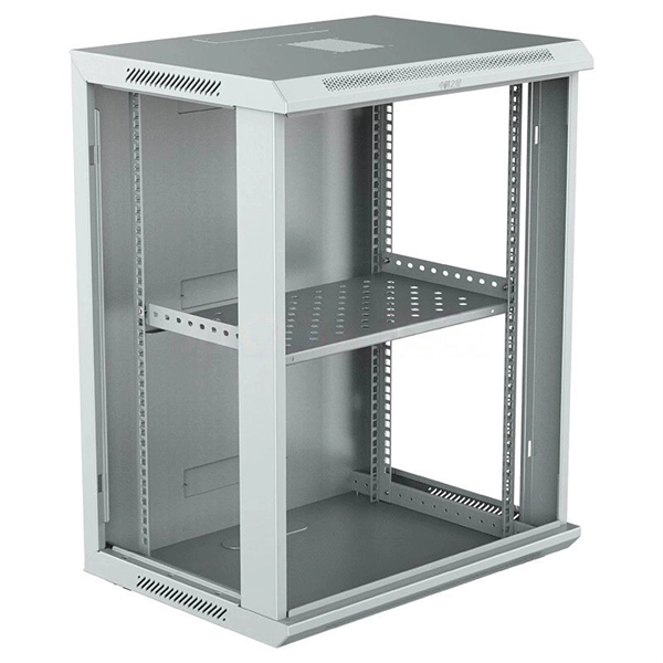
Telecom Racks & Cabinets
19-inch racks, wall-mount cabinets, open frames with high load capacity and seismic rating.
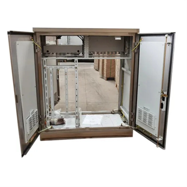
Outdoor Climate Cabinets
IP55/IP66 outdoor enclosures with integrated cooling/heating, -40°C to +55°C operation.
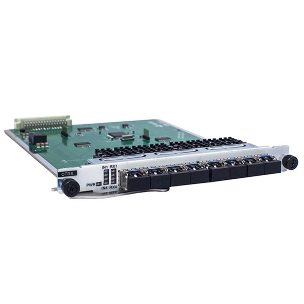
Smart PDUs & Power Distribution
Intelligent PDUs with remote monitoring, per-outlet switching, and environmental sensors.
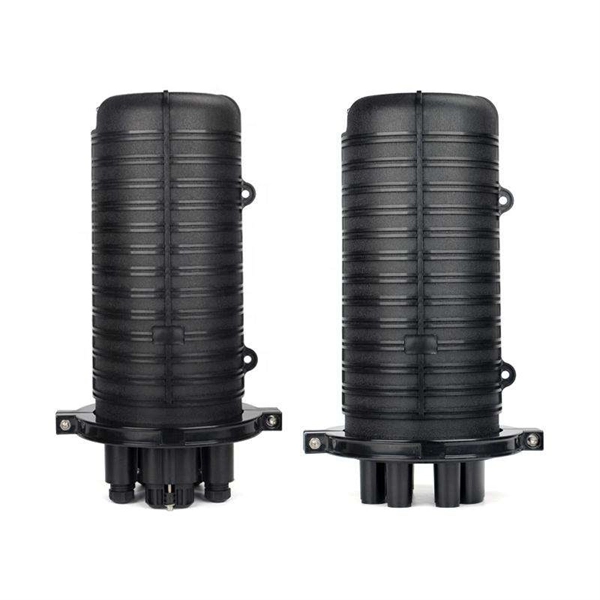
Shelters & Network Cabinets
Prefabricated telecom shelters, emergency comms shelters, and network cabinets with cable management.