-
Fiber Optic Cable Dispersion Test Method
CD-PMD testing is a critical testing method used in optical fiber communication systems to measure and mitigate the effects of chromatic dispersion (CD) and polarization mode dispersion (PMD). Fibers can be fusion spliced with virtually no loss. Dense wavelength division multiplexing (DWDM) allows up to 128 channels of signals on a single fiber. However, for. this document is the property of JDSU. No part of this book may be reproduced or utilized in any form or means, electronic or mechanical, including photocopying, recording, or by any information storage and retrieval system, without pe n optical fiber to a distant receiver. Since transmitters are actually made up of several wavelengths and each wavelength travels at a different speed, the difference in arrival time of each. he JDSU Reference Guides to Fiber Optic its capability for long distance high speed communications. Attenuation at long wavelengths low.
[PDF Version]
-
How to calculate the loss from cutting a telecommunications fiber optic cable
The loss budget formula adds fiber length, connector/splice losses, and a safety margin (usually 3 dB). • Use worst-case estimates and validate with actual measurements. A tool that computes how many fibers fit in a circular bundle and splits them into user-defined segments for cable-assembly planning. Key Parameters: • Center Diameter, Fiber Diameter, Packing Efficiency, Section Count Calculation: Visualization: • Color-coded radial diagram with per-section. To ensure a fiber optic link operates correctly, you need to calculate its loss, power budget, and power margin. The calculation methods are as follows. In fiber optic cabling, it is often necessary to calculate the maximum loss over a certain length of line. After entering your values, please ensure you click the 'Calculate Link Loss' button at the bottom of the page to generate your total link loss.
[PDF Version]
-
How to test fiber optic cable locations
Effective fiber testing utilizes advanced tools such as Optical Loss Test Sets (OLTS), Optical Time-Domain Reflectometers (OTDR), and Visual Fault Locators (VFL) to diagnose and correct issues, ensuring optimal network performance. As a nationwide provider of managed network services, TailWind performs fiber testing across hundreds of sites to help multi-location businesses stay connected with confidence. In this guide, we'll walk through how to test fiber optic cable and best practices to simplify your next fiber test. Related: Fiber Optic Connectors – Identification Guide Regularly testing fiber optic cables helps minimize network downtime, lengthens the network's longevity, reduces maintenance. For every fiber optic cable plant, you will need to test for continuity, end-to-end loss and then troubleshoot the problems. By identifying potential issues early, you can enhance.
[PDF Version]
-
What to do if the fiber optic cable splice loss is too high
If high loss persists, inspect the splicer's alignment system. Clean the V-grooves and objective lenses with appropriate cleaning sticks and isopropyl alcohol. Dirt or dust on the fibre ends is one of the most common causes of high splice loss. Fusion splicers have settings that must be tailored to your fibre type and condition. Modern fiber optic networks usually keep splice loss low, as shown below: You should know that each splice can add 0. Understanding its causes and solutions is critical for reliable fiber optic installations. Poor Fiber Cleave: Angled or chipped cleaves prevent proper. Neglecting minor problems can lead to higher splice losses, increased signal attenuation, and long-term damage to fibre networks. This. One problem I continue to see is unexpected high loss during spicing between exchange-to-exchange network, particularly in the feeder and backbone segments, which can seriously impact the performance of the PON networks.
[PDF Version]
-
Why is data transmission slow in single-mode fiber optic cables
As pulses of light travel down a fiber optic cable, they can get stretched, distorted, and blurred. Lasers generate a single wavelength of light, which travels in a straight line through the single-mode fiber. Compared to multimode fiber, single-mode fiber has a higher bandwidth and can carry signals for longer distances. Long lines need repeaters, or you risk signal drop. Matching your fiber optic cable with modern tech. Unlike copper cables, which rely on electrical signals, fiber optics use pulses of light to transmit data—offering unmatched bandwidth, low interference, and long-distance capabilities. Multi-mode fibers, while capable of higher data rates over short distances, are prone to modal dispersion, which can slow. Single-mode fiber optic cables single-mode fiber optic cables 1 have a small core, typically around 9µm, and are designed to carry signals over long distances at higher bandwidths. They feature low attenuation benchmarks 2 and minimal dispersion. They use OS1 or OS2 OS1 or OS2 classifications to.
[PDF Version]
-
Maximum loss of a single fiber optic cable connector
Acceptable dB loss for fiber depends on the component you're measuring: a single mated connector pair should lose no more than 0. 75 dB, a fusion splice should stay under 0. To be able to judge whether a fiber optic cable plant is good, one does a insertion loss test with a light source and power meter and compares that to an estimate of what is a reasonable loss for that cable plant. The estimate, called a "loss budget" is calculated using typical component losses for. At TREND Networks, we are frequently asked how much loss is allowed when conducting testing on fibre optic cabling. Unfortunately, it is not a simple answer and depends on several factors. Optical. Use this worksheet to input values for all variables that will impact your system's performance.
[PDF Version]
-

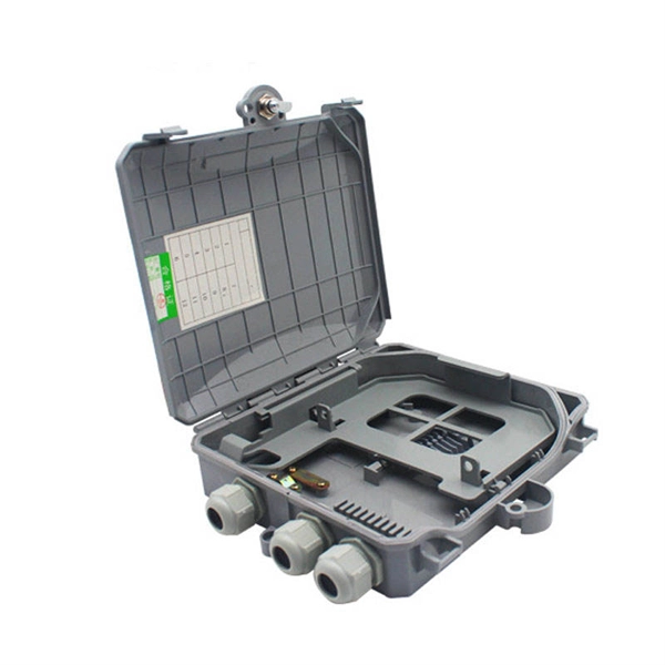
How to transmit data using a fiber optic terminal box
Learn how to install a fiber optic termination box step-by-step for FTTH projects. Covers mounting, splicing, routing, labeling, and testing for indoor/outdoor use. Proper installation and maintenance of FTBs are essential to ensure the reliability and performance of the network infrastructure. Before. Fiber optic technology has revolutionized the telecommunications industry, enabling faster and more reliable data transmission.
[PDF Version]
-
User fiber optic cable test below 24
Fiber testing is the process of verifying the performance of optical fiber cabling. This process includes a range of tests and measurements such as insertion loss, optical return loss, and fiber length. It encompass.
[PDF Version]
-
Multimode fiber optic splice loss standard
For multimode fiber, the loss is about 3 dB per km for 850 nm sources, 1 dB per km for 1300 nm. 5 dB/km max per EIA/TIA 568) This roughly translates into a loss of 0. Splicing is required to create a continuous path for light transmission from one fiber to another. Two different methods exist for splicing fibers: Typical splice loss values (the measure of loss in optical power across the splice point) are usually lower for fusion splices (typically less than 0. 1. To be able to judge whether a fiber optic cable plant is good, one does a insertion loss test with a light source and power meter and compares that to an estimate of what is a reasonable loss for that cable plant. The estimate, called a "loss budget" is calculated using typical component losses for. Acceptable dB loss for fiber depends on the component you're measuring: a single mated connector pair should lose no more than 0. 75 dB, a fusion splice should stay under 0. 5 dB per kilometer depending on the type and wavelength. The Contractor must utilize the correct equipment and testing techniques to gain acceptance, or the work cannot be approved. Optical fiber splicing is a critical.
[PDF Version]
-
South Korean Fiber Optic Cable Loss Standards
Multimode Fiber: Typical allowable loss is 2. 9 dB for short-distance installations (100–300 meters). To be able to judge whether a fiber optic cable plant is good, one does a insertion loss test with a light source and power meter and compares that to an estimate of what is a reasonable loss for that cable plant. The estimate, called a "loss budget" is calculated using typical component losses for. Using an optical power meter and light source or OLTS (Optical Loss Test Set), Tier 1 Certification can be performed against industry standard limits for cable and connectors. Fiber optic testing of a newly installed system not only verifies that the system meets its design requirements, but also creates a performance baseline for all future testing and troubleshooting of t at system. The Contractor must utilize the correct equipment and testing techniques to gain acceptance, or the work cannot be approved. This testing. Fiber Loss Limits Understanding fiber loss is vital in maintaining a reliable, efficient network. Fiber loss, or attenuation, refers to the reduction in optical power as light travels through a fiber optic cable.
[PDF Version]
-
Custom Process for 24-Core Fiber Optic Splices for Data Centers
The diagram of 24 core fiber fusion splicing sequence is an essential tool for engineers in the telecommunications industry. This article provides a detailed explanation of the sequence, covering four aspects: preparation, stripping and cleaning, fusion splicing, and. Whether you need fusion splicing for permanent, ultra-low-loss connections or mechanical splicing for rapid field deployment, our certified technicians deliver factory-quality results on every job — from hyperscale data centers and carrier-grade telecom networks to enterprise campus infrastructure. As networks grow larger, denser, and more complex, fiber optic splicing becomes a critical path activity that directly impacts time‑to‑light, network reliability, and long‑term operating costs. Therefore, we will also touch on cost factors, risk management, and best practices in. Fusion splicing is the bedrock of high-performance fiber optic networks, enabling seamless signal transmission through permanent, low-loss fiber joins. This field technician tutorial shows the real splicing process, core alignment, and best practices to.
[PDF Version]
-
Actual test of fiber optic cable tapping device
Test equipment can simply put a bend in the fiber and extract sufficient light to identify a fiber or determine if a signal is present.OverviewFiber tapping is a method that extracts signal from an without breaking the connection. Tapping of optical fiber entails diverting some of the signal being transmitted in the core of the fiber into anothe. Surreptitious fiber tapping may be used for surveillance, particularly in jurisdictions where specific authorities are legally granted access (usually limited or conditional) to electronic equipment used in One way to detect fiber tapping is by noting increased added at the point of tapping. Some systems can detect sudden attenuation on a fiber link and will automatically raise an alarm. There are, however, ta.
[PDF Version]
-
Average Loss of Power Fiber Optic Cables
Use this worksheet to input values for all variables that will impact your system's performance. To be able to judge whether a fiber optic cable plant is good, one does a insertion loss test with a light source and power meter and compares that to an estimate of what is a reasonable loss for that cable plant. The estimate, called a "loss budget" is calculated using typical component losses for. At TREND Networks, we are frequently asked how much loss is allowed when conducting testing on fiber optic cabling. Unfortunately, it is not a simple answer and depends on several factors. This step is necessary to see if your system falls within. Fiber optic loss, also known as optical attenuation, refers to the light loss between the transmitter and receiver. While some loss is expected, excessive or unexpected loss can lead to poor.
[PDF Version]
-
Fiber optic patch cord storage requirements
The maximum storage temperature is specified for each cable in the datasheet and must be respected. Reels should be stored in areas with flat firm surfaces to prevent damage. GT-SCSCDM4A-xM fiber optic patch cords are ideal for short distance patching applications. These fiber optic cables have been built to exceed industry standards tested for insertion loss and reflectance on within UL certified OFNR (Riser) rated jacket with Kevlar yarn, and are factory terminated. Network decision-makers must evaluate several technical specifications before standardizing an MPO patch cable bill of materials: 1. Using Base-12 cables for Base-8 transceivers leaves 33% of. Whether you're cabling a new AI training cluster, upgrading a campus backbone, or just replacing aging patch cords in a colocation cabinet, this guide walks you through every decision point with actionable criteria. 1 What Is a Fiber Optic Patch Cable? 1. FO-VC2 JOINT USE - VERICAL MIDSPAN CLEARANCES 48. They are manufactured and tested in compliance with TIA 604 (FOCIS), IEC 61754 and YD/T industry standards.
[PDF Version]
-
Correct insertion and removal of fiber optic patch cords
Here's a detailed guide on how to install and terminate fiber patch cords: Ensure that you have the correct type and length of fiber patch cord for your application. Verify. Correct patch-cord installation is essential for maintaining low insertion loss, stable return loss, and long-term reliability in both indoor and outdoor fiber networks. Keep everything clean by checking connectors often. Clean them to stop dust from building up. This guide addresses expert-certified best practices applied by professionals in the telecommunications, data. Fiber optic can be installed in the same topology as copper cable using distribution frames and switches. Long-distance cables are typically laid as trunks or rings with repeaters or amplifiers between cable segments to strengthen the signal. Whether you're connecting a data center, a corporate network, or a high-density fiber infrastructure, correct installation methods are essential.
[PDF Version]
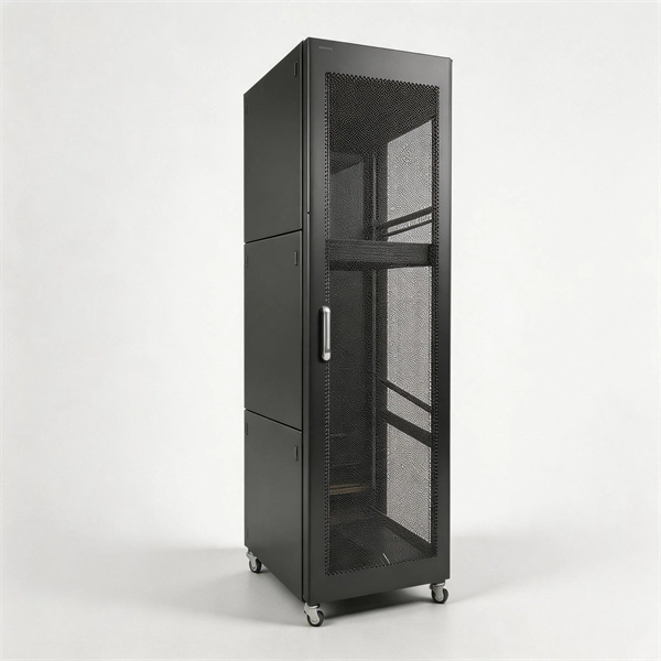
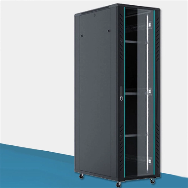
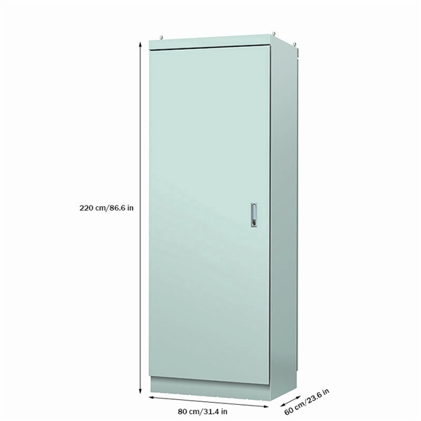
Telecom Racks & Cabinets
19-inch racks, wall-mount cabinets, open frames with high load capacity and seismic rating.
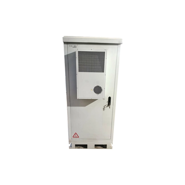
Outdoor Climate Cabinets
IP55/IP66 outdoor enclosures with integrated cooling/heating, -40°C to +55°C operation.
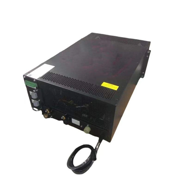
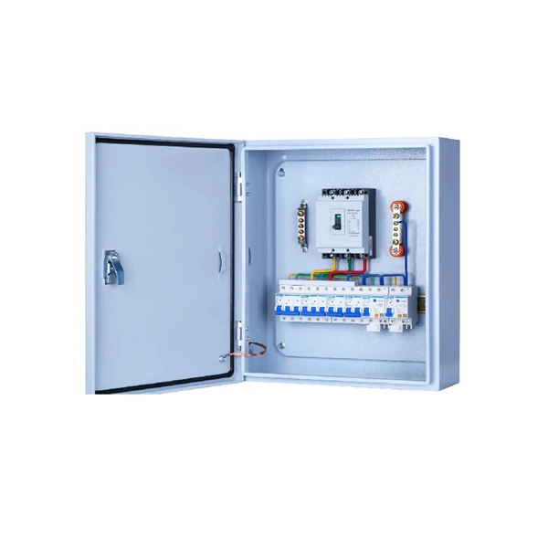
Smart PDUs & Power Distribution
Intelligent PDUs with remote monitoring, per-outlet switching, and environmental sensors.
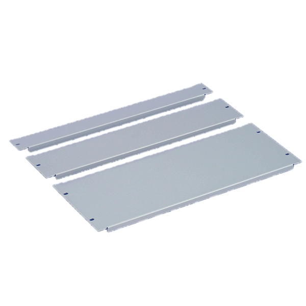
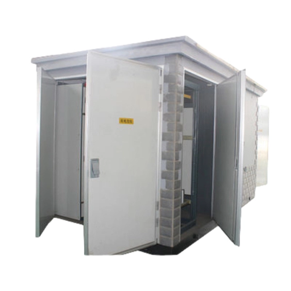
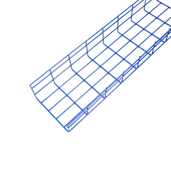
Shelters & Network Cabinets
Prefabricated telecom shelters, emergency comms shelters, and network cabinets with cable management.