-
Function of Fiber Optic Cold Splice Terminal Connector
Fiber optic cold connection, also known as mechanical splicing, is a widely used method of connecting optical fibers in a network. Unlike fusion splicing, which uses heat to join two optical fibers together, cold connection uses mechanical means to create a stable and low-loss. Should you use connectors or splices? In this lesson, a long and very important one, you will learn about fiber splicing and termination. Fiber optic joints or terminations are made two ways: 1) splices which create a permanent joint between the two fibers or 2) connectors that mate two fibers to. Fiber optic joints or terminations are made two ways: 1) splices which create a permanent joint between the two fibers or 2) connectors that mate two fibers to create a temporary joint and/or connect the fiber to a piece of network gear. In this. Executive Summary: A fiber optic pigtail is one of the most commonly specified yet least understood components in structured cabling.
[PDF Version]
-
Fiber Optic Cold Splice Installation
This step-by-step fiber optic cold splicing tutorial makes it easy for beginners and professionals. They protect and organize the sensitive connection points between optical fibres and play a decisive role in the quality, reliability and ease of maintenance of the entire network. While connectors. Optical fiber Lengjie is used for optical fiber butt optical fiber or optical fiber docking pigtail, which is equivalent to making a joint, (fiber docking pigtail refers to the butt joint between the optical fiber and the core of the pigtail, not the pigtail head mentioned by the former), used for. Fiber optics is the fastest and one of the safest ways to transmit information online.
[PDF Version]
-
Fiber optic cold splice temperature resistance
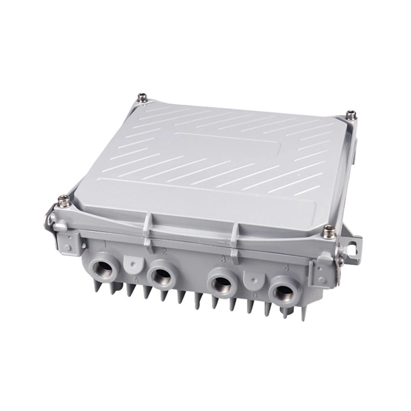
The closure works in -35° C to 70°C environments, is cold and heat resistant, ofers electrical insulation, and is resistant to chemical corrosion. Note: Any fiber count upto 96F can be accomodated in this closure. The fiber optic dome splice closure is well-suited for splicing, distributing variable optical cables, and splitting. The solid box shell and the main structure are built to withstand harsh environments. The dome closure also protects fiber optic cables from vibration, impact, stretching, twisting. Optical fiber's ability to withstand extreme heat and cold directly impacts signal integrity, network reliability, and maintenance costs, especially in harsh environments like industrial facilities, outdoor installations, and data centers. This comprehensive guide answers the question: “How much. Abstract—This study explores the efficacy of thermal splicing conditions between silica and zirconium-fluoride fibers, focusing on achieving mechanical strength between the two fibers. Moreover, this is for 48 single fusion splices. These devices use mechanical closures.
[PDF Version]
-
The function of fiber optic cold connector converters
Its primary function is to transform electrical signals that are used in copper cables to optical signals that are used in fiber cables and reverse the process. They help to bridge the gap between Copper-based Ethernet or fiber-optic systems, which have fast rates. If you're building a new data infrastructure, expanding your industrial setup, or upgrading your CCTV systems, knowing the importance. A fiber media converter is a network device that seamlessly connects different types of cabling, most commonly converting between copper-based Ethernet and fiber optic cables, allowing for the extension of network distances and improved data transmission. A media converter overview shows these devices keep your network strong and steady.
[PDF Version]
-
Connection method of cold connector for telecommunications fiber optic socket
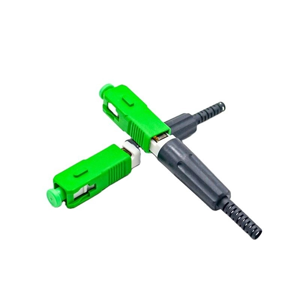
Optical fiber fast connectors, also known as cold connectors, are becoming increasingly popular due to their ease of use and quick installation. Unlike traditional fiber connectors that require epoxy and polishing, fast connectors use a mechanical splice to join the fibers. Proven mechanical splice technology ensuring precision fiber alignment, a factory pre-cleaved fiber stub and a proprietary index-matching gel combine to. Active connection utilizes various fiber optic connectors (plugs and sockets) to connect site-to-site or site-to-cable. The typical attenuation is 1dB per connection. It allows connections. Fiber optic joints or terminations are made two ways: 1) splices which create a permanent joint between the two fibers or 2) connectors that mate two fibers to create a temporary joint and/or connect the fiber to a piece of network gear.
[PDF Version]
-
How much optical attenuation does a fiber optic cold connector cause
This calculator helps you estimate the total attenuation (signal loss) in a fiber optic cable link. Here are the details and instructions about each field and how they contribute to the calculation: 1. Attenuation Coefficient (dB/km):Fiber loss, also called fiber optic attenuation or attenuation loss, refers to the loss of signal between input and output. Losses can be introduced by various means such as intrinsic material absorption, scattering, bending, connector loss and more. While some loss is expected, excessive or unexpected loss can lead to poor performance, network. The attenuation of the optical fiber is a result of two factors, absorption and scattering. In this article we'll discuss.
[PDF Version]
-
Which brand of fiber optic cold connector should I use
Whether you are installing a brand new fiber optic network or you are repairing a legacy system, using this fiber optic connector guide will help you determine what kind of connector you are looking at or what type of connector you need to replace. A fiber fast connector, also known as a mechanical splice or cold connector, is a field-installable connector that terminates fiber optic cables without requiring a fusion splicer. Proven mechanical splice technology ensuring precision fiber alignment, a factory pre-cleaved fiber stub and a proprietary index-matching gel combine to. If you need a fast answer on which fiber optic connector to specify for your project, here is the executive summary: For 400G-800G Data Centers: Choose MTP/MPO connectors. They dominate hyperscale parallel optics due to massive multi-fiber density. They are used to connect fiber optic cables to transmit data over long distances, and they come in different types such as SC, LC, ST, and FC connectors.
[PDF Version]
-
Can a fiber optic cold connector be used if it is not bent
A suitable connector, which is specifically designed for harsh environments, can ensure the fiber conduit is sealed, and the fiber itself is safe from the risk of ice formation. There are three common types of fiber connectors: SC, ST (bayonet-twist) and LC (push-pull. Fiber optic cold connection, also known as mechanical splicing, is a widely used method of connecting optical fibers in a network. In this. However, fiber links can fail or degrade due to connector contamination, cable damage, excessive bending, or splice deterioration. Systematic troubleshooting requires the right tools and a methodical approach. The causes are usually lack of training, lack of practice and lack of understanding of what is a “good” and/or “acceptable” fiber optic connector. Both techniques have their advantages and are suited for different applications, but understanding which method to use can greatly impact the network's. To mitigate this problem, one approach is to only install fiber cables buried below the frost line, so there is no threat of ice. Another solution can be to add.
[PDF Version]
-
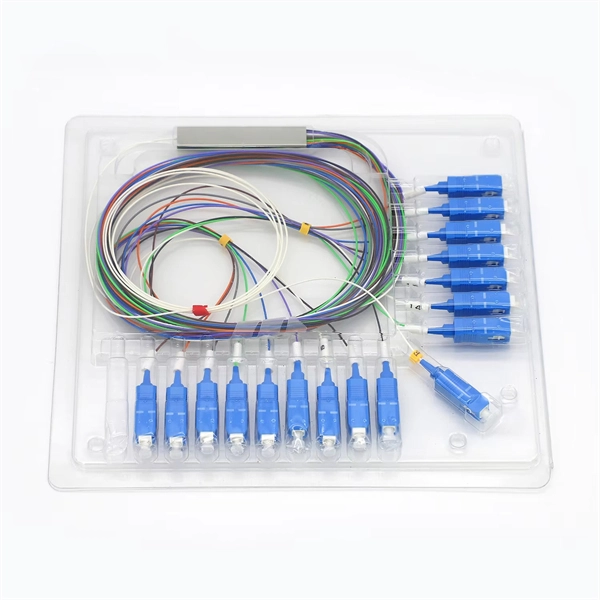
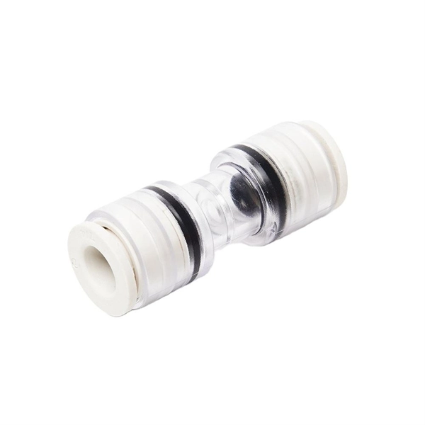
6-core fiber optic cold splice from a supplier in the 10 ASEAN countries
Explore reliable optical fiber splice closures for network deployment. Our closures prioritize reliability, installability, and flexibilitySingle-core fiber optic cables have a core diameter of 8 to 10 microns and one thin glass strand. They use only one core to transmit data, providing an exceedingly clear signal over long distances. Because of their low signal attenuation, they are ideal for long-distance telecommunications and data. Used for fiber butt splicing fiber or fiber splicing pigtail, this is equivalent to making a splice, and the thing used for this kind of cold splicing is called an optical fiber cold splice. They also offer FBA freight services. Durable ABS material, 3-year warranty. FIS' New CA6+ Core Alignment Fusion splicer is the latest addition to the FIS Fusion Splicing product line. With the Contractor always in mind, the CA6+ is faster, more durable, and easier to use than ever. Fully compatible with FIS Cheetah and Armordillo Splice-On Connectors, this is the perfect.
[PDF Version]
-
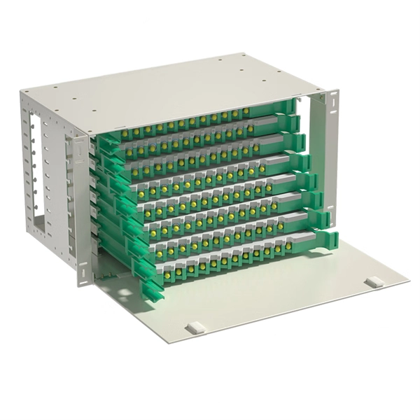
Number of fiber optic connector cores
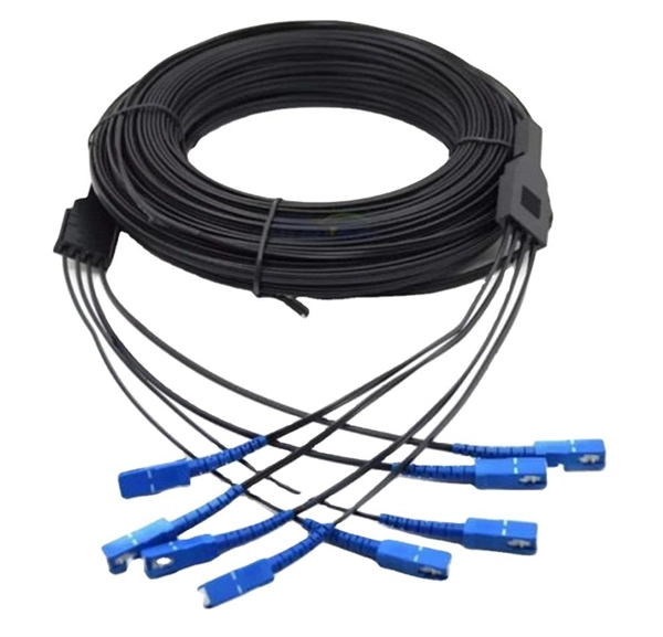
Multimode fiber optic cables can have multiple cores, commonly 2 or 4. The number of cores refers to the individual strands within the cable that carry the optical signals. These cores allow for the transmission of multiple signals simultaneously, increasing the capacity and. The number of optical cores in an optical fiber is the total number of equipment interfaces multiplied by 2, plus 10% to 20% of the spare quantity, and if the communication mode of the equipment has serial communication and equipment multiplexing, you can reduce the number of cores. Made from either high-quality. At TARLUZ, we understand that selecting the right fiber core count is critical for network performance, scalability, and cost-effectiveness. They are typically made of high-quality glass.
[PDF Version]
-

Is the failure rate of fiber optic cold connectors high
If you've ever stood in a data center cold aisle or a roadside splice closure, you know the truth: fiber doesn't fail in the middle of the cable. It fails where we touch it—where glass meets human hands, where theory meets dust, humidity, and haste. Understanding the common causes of failure and implementing preventive measures is essential to maintaining reliable networks and avoiding costly downtime. In this. Fiber optic patch cords are often treated as low-risk consumables, yet a large percentage of optical link failures originate at the patch cord level. Unlike backbone cables, patch cords are frequently connected, disconnected, bent, and handled by technicians, making them the most vulnerable. Fischer Connectors offers not only standardized products that operate within certain temperature ranges, e. Physical damage is one of the most frequent causes of fiber.
[PDF Version]
-
Fiber Optic Circuit Rotary Connector
A fiber optic rotary joint, also known as a fiber optic slip ring or rotary coupler, is a device that allows the transmission of light signals through an optical fiber while allowing rotation between two connected parts. SPINNER builds fiber-optic rotary joints (FORJs) available up to 109 channels and any fiber type: single-mode, multi-mode or large-core. They are designed for applications where electrical slip rings alone cannot. nced Slip Rings & Rotary Joints. Our innovative (patented) designs ensure unmatche ��s most demanding environments.
[PDF Version]
-
What to do if the fiber optic cable splice loss is too high
If high loss persists, inspect the splicer's alignment system. Clean the V-grooves and objective lenses with appropriate cleaning sticks and isopropyl alcohol. Dirt or dust on the fibre ends is one of the most common causes of high splice loss. Fusion splicers have settings that must be tailored to your fibre type and condition. Modern fiber optic networks usually keep splice loss low, as shown below: You should know that each splice can add 0. Understanding its causes and solutions is critical for reliable fiber optic installations. Poor Fiber Cleave: Angled or chipped cleaves prevent proper. Neglecting minor problems can lead to higher splice losses, increased signal attenuation, and long-term damage to fibre networks. This. One problem I continue to see is unexpected high loss during spicing between exchange-to-exchange network, particularly in the feeder and backbone segments, which can seriously impact the performance of the PON networks.
[PDF Version]
-
Multimode fiber optic splice loss standard
For multimode fiber, the loss is about 3 dB per km for 850 nm sources, 1 dB per km for 1300 nm. 5 dB/km max per EIA/TIA 568) This roughly translates into a loss of 0. Splicing is required to create a continuous path for light transmission from one fiber to another. Two different methods exist for splicing fibers: Typical splice loss values (the measure of loss in optical power across the splice point) are usually lower for fusion splices (typically less than 0. 1. To be able to judge whether a fiber optic cable plant is good, one does a insertion loss test with a light source and power meter and compares that to an estimate of what is a reasonable loss for that cable plant. The estimate, called a "loss budget" is calculated using typical component losses for. Acceptable dB loss for fiber depends on the component you're measuring: a single mated connector pair should lose no more than 0. 75 dB, a fusion splice should stay under 0. 5 dB per kilometer depending on the type and wavelength. The Contractor must utilize the correct equipment and testing techniques to gain acceptance, or the work cannot be approved. Optical fiber splicing is a critical.
[PDF Version]
-
Which fiber optic connector supplier in Nepal is the best
Search results of Top 12 Cabling and Fibre Optics Companies in Nepal, near me. Listings are verified with accurate business information. Ltd was established in 2017 with an objective to provide end-to-end fiber optic products and solutions to Internet Service Providers (ISPs) and Cable TV Operators in Nepal; and also supplying telecommunication equipment. We mostly import goods directly from our partner. Nepal - Shop for Best Online at Daraz. Great Prices, Even Better Service. Your go-to for IT networking and management solutions. Comprehensive. We are proudly Introducing our fast connectors at eman communications revolutionizing fiber optic installations with their factory pre-polished design. Lalitpur alone represents.
[PDF Version]
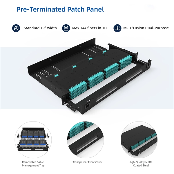
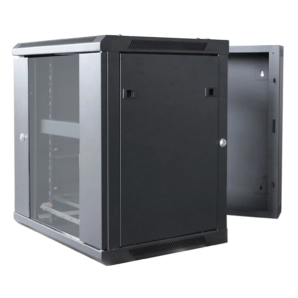
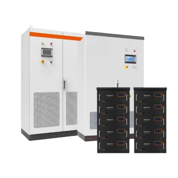
Telecom Racks & Cabinets
19-inch racks, wall-mount cabinets, open frames with high load capacity and seismic rating.
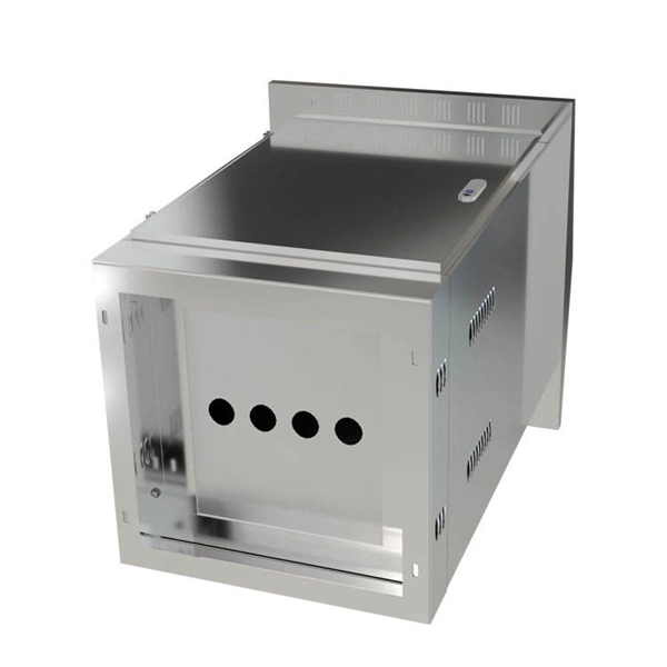
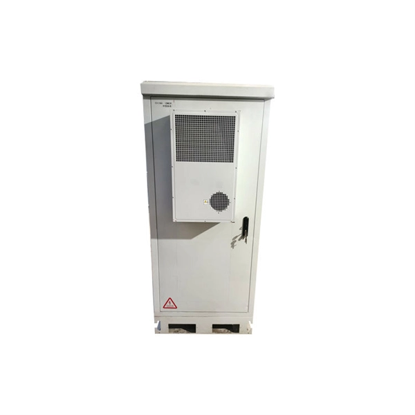
Outdoor Climate Cabinets
IP55/IP66 outdoor enclosures with integrated cooling/heating, -40°C to +55°C operation.
Smart PDUs & Power Distribution
Intelligent PDUs with remote monitoring, per-outlet switching, and environmental sensors.
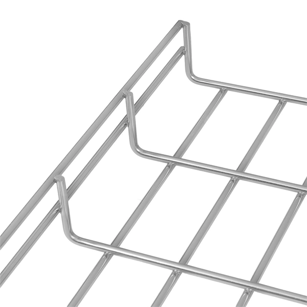
Shelters & Network Cabinets
Prefabricated telecom shelters, emergency comms shelters, and network cabinets with cable management.