-
Performance Comparison of Low Insertion Loss Splitter Remote Monitoring Type and Selection Guide
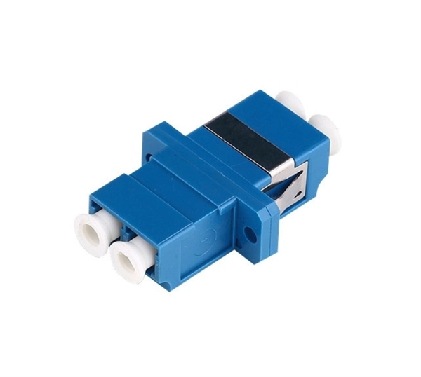
This guide focuses on two critical aspects of optical splitters that define FTTH performance: split ratios (how signals are divided) and splitting architectures (how splitters are deployed). In fiber-optic networks like FTTx and PON, PLC splitters are key components for distributing optical signals to multiple users. However, each splitter has complex parameters, including insertion loss, return loss, polarization-dependent loss, and uniformity. They have been used since the 1980s to create networks and provide the technology for today's passive optical networks used in fiber to the home. Planar Lightwave Circuit (PLC) splitters are essential passive devices in modern fiber-to-the-home (FTTH) networks. Although often viewed as a simple passive device, the choice of splitter type, split ratio, and connector interface has a direct impact on network performance, scalability, installation efficiency, and long-term operational cost.
[PDF Version]
-
Swiss Export Price for Remote Power Supply with Low Loss CIF
This page provides - Switzerland Export Prices - actual values, historical data, forecast, chart, statistics, economic calendar and news. In this section, you will find numerous tables and charts, and information on Swiss imports and exports. Swiss foreign trade posted increases in both directions of trade in 2025. 0 billion, a new. ITC's Trade Map is an online database on international trade statistics, providing an array of useful indicators on export performance, international demand, alternative markets and the role of competitors from both the product and country perspectives. Index of export market penetration is 0. 94 points from 1993 until 2026, reaching an all time high of 116. 50 points in July of 2008 and a record low of 99.
[PDF Version]
-
Red light source with low loss
In this article, you'll find an in-depth look at six of the best FDA-cleared red light therapy devices available to consumers. Red light therapy is a treatment that may help skin, muscle tissue, and other parts of your body heal. It uses low levels of red light to target your skin and cells. Can it be used safely? How is it changing the body at a cellular level? And, oh yeah: Are. DCReport looks at the legitimacy of red light therapy as a solution for hair loss. Image: Courtesy of GroWell Red light therapy for hair loss has gone mainstream — promoted by dermatologists and other hair restoration physicians, sold directly to consumers, and marketed across social media as a. Red light therapy (RLT) is gaining popularity for its wide range of health benefits. As a functional health practitioner who has seen firsthand the impact of RLT on my clients, I find it to be.
[PDF Version]
-
Finnish earthquake-resistant server racks with low loss
Designed for stability and durability, these modular racks are tested and certified to GR-63-CORE standards to help maintain uptime, safeguard personnel, and reduce the risk of equipment damage during seismic events. NEBS GR 63-Core certified zone 4 cabinets for earthquake prone or areas subject to regular vibrations, such as airports, factories and high rise buildings. Solid sided construction, 2 pair of fully adjustable mounting rails, Seismic bolt down base with cable access holes, top panel with cable. SR42UBZ has been designed and tested to meet Telcordia GR-63-CORE Network Equipment & Building Systems (NEBS) requirements for Zone 4 Seismic Earthquake Environments. For Optical Distribution Frame installations, DCX Seismic Cabinets. Our helpful IT Pros make finding your server rack cabinets, power, cooling and all your IT accessories a success. Order online with same day shipping for most products.
[PDF Version]
-
Performance Comparison of Low Insertion Loss Splitter CWDM and Which is Better
Discover how CWDM Demux works, compare key specifications across brands, and learn why C-LIGHT CWDM Demux delivers lower insertion loss, higher isolation, and better reliability for modern fiber networks. What is a CWDM Demux? A CWDM Demux (Coarse Wavelength Division Multiplexer Demultiplexer) is a passive optical device that separates multiple wavelengths transmitted over a single fiber into individual channels. By comparing CWDM vs DWDM vs MWDM vs LWDM vs SWDM, you can make an informed decision to ensure your network meets your data capacity, distance, and application requirements. Choosing the right wavelength division multiplexing technology guarantees optimal network performance tailored to your needs. Insertion loss plays a decisive role in both CWDM and DWDM optical networks. These wavelengths are usually between the C band (1525-1565 nm) and.
[PDF Version]
-
Maximum loss of a single fiber optic cable connector
Acceptable dB loss for fiber depends on the component you're measuring: a single mated connector pair should lose no more than 0. 75 dB, a fusion splice should stay under 0. To be able to judge whether a fiber optic cable plant is good, one does a insertion loss test with a light source and power meter and compares that to an estimate of what is a reasonable loss for that cable plant. The estimate, called a "loss budget" is calculated using typical component losses for. At TREND Networks, we are frequently asked how much loss is allowed when conducting testing on fibre optic cabling. Unfortunately, it is not a simple answer and depends on several factors. Optical. Use this worksheet to input values for all variables that will impact your system's performance.
[PDF Version]
-
AC to DC power supply cold aisle low loss manufacturers
IQS Directory provides a comprehensive list of ac to dc converter manufacturers and suppliers. Low noise, efficient, reliable and easy to integrate power supplies are essential in medical device, semiconductor fabrication and industrial technology applications. Our broad range of cost-effective AC-DC power solutions includes flexible, configurable and custom products ranging from 3W to 3kW. Pico offers a comprehensive range of DC-DC converters with ultra-miniature, high-reliability designs featuring output voltages up to 10kV, output power up to 300 Watts, input voltage ranges up to 1200V and operating temperatures as wide as -55°C to +85°C for critical applications in aerospace. Cincon offers a range of robust, low-profile AC/DC power supplies tailored for various applications, all with a height of 1 inch. These supplies span power outputs from 200W to 750W and are available in semi-potted chassis type. With our newest addition, the LFM series, we provide both industrial. Daitron's state-of-the-art ultra low-noise power supply is ideal for systems that require low-noise environments.
[PDF Version]
-
Long-distance optical transceivers with low loss 2026 model CE certified
Explore the critical role of telecom grade C-band transceivers in long-distance optical transmission, with specs, deployment insights, and expert guidance. Compared with 850nm or 1310nm SFP modules, 1550nm SFPs are designed for scenarios where signal attenuation, link budget. In the modern network, transceivers are categorized primarily by their reach (distance) and media type (Multimode vs. Miscalculating these distances leads to bit errors and link failures that can cripple a mission-critical environment. Hyperscale Data Centers: High-density spine-leaf. In the rapidly evolving landscape of hyperscale data centers, 5G Open-RAN architectures, and enterprise campus backbones, the optical transceiver has graduated from a commodity component to a critical strategic asset. From short-reach SR4 (hundreds of meters) to intermediate-reach LR4 (up to 10 kilometers), and further to. The Innoptical's IN-C2DCO-200G-LH coherent module, utilizes a trio of indium phosphide (InP) based PICs, covering the laser, modulation, and receiver functions. Through integration, we have enabled almost complete on-wafer test of our PICs. We have a FAE team to provide tailor-made network.
[PDF Version]
-
How do I switch the fiber optic cable to red light source mode
Turn on the optical visual fault locator. Most VFLs have a button or switch to turn on the light. You should see a visible red light coming from the fiber. Pay close attention to areas where the light is leaking or where it seems. A VFL is used to detect faults, breaks, or bends in fiber optic cables by emitting a bright red light that is visible even through the fiber's jacket. The button at the top of the device (with a red ring around it) is the on-off switch. This cable continuity tester helps find breaks in cables, connectors and splices. Compatible with. VFL usually uses red visible light (635-650nm) laser light source, and the optical output power of the laser is usually 1mW or less. You can see red light with the naked eye, but due to the high light output power, you should remember not to look directly at the output of the VFL. Using a VFL to diagnose issues can save time and cost when diagnosing an.
[PDF Version]
-
How to measure the polarization loss of an optical splitter
Attach the light source launch to the splitter and attach a receive launch reference cable to the output and the optical power meter, and then measure the loss. The polarization state describes the orientation of the electric field vector of a light wave. It can vibrate along a fixed direction (linear polarization). What you are measuring is the loss of the splitter due to the split ratio, excess loss from the manufacturing process used to make the splitter and the input and output connectors.
[PDF Version]
-
Average Loss of Power Fiber Optic Cables
Use this worksheet to input values for all variables that will impact your system's performance. To be able to judge whether a fiber optic cable plant is good, one does a insertion loss test with a light source and power meter and compares that to an estimate of what is a reasonable loss for that cable plant. The estimate, called a "loss budget" is calculated using typical component losses for. At TREND Networks, we are frequently asked how much loss is allowed when conducting testing on fiber optic cabling. Unfortunately, it is not a simple answer and depends on several factors. This step is necessary to see if your system falls within. Fiber optic loss, also known as optical attenuation, refers to the light loss between the transmitter and receiver. While some loss is expected, excessive or unexpected loss can lead to poor.
[PDF Version]
-
How much loss is there in an optical cable connector
A typical fiber connector has an insertion loss of around 0. How can insertion loss be measured? A common method is optical time-domain reflectometry, which can separately measure the loss of multiple. Insertion loss, also known as attenuation, is the loss of optical power that occurs when light passes through a fiber optic connector. It is caused by factors such as misalignment, air gaps, and imperfections in the connector components. Unfortunately, it is not a simple answer and depends on several factors. This article explores various connector types—such as SC, LC, FC, ST, APC, and UPC—and analyzes how their design and polishing affect IL and RL performance. Insertion Loss (IL): Measures the. Fiber loss, also called fiber optic attenuation or attenuation loss, refers to the loss of signal between input and output.
[PDF Version]
-
South Korean Fiber Optic Cable Loss Standards
Multimode Fiber: Typical allowable loss is 2. 9 dB for short-distance installations (100–300 meters). To be able to judge whether a fiber optic cable plant is good, one does a insertion loss test with a light source and power meter and compares that to an estimate of what is a reasonable loss for that cable plant. The estimate, called a "loss budget" is calculated using typical component losses for. Using an optical power meter and light source or OLTS (Optical Loss Test Set), Tier 1 Certification can be performed against industry standard limits for cable and connectors. Fiber optic testing of a newly installed system not only verifies that the system meets its design requirements, but also creates a performance baseline for all future testing and troubleshooting of t at system. The Contractor must utilize the correct equipment and testing techniques to gain acceptance, or the work cannot be approved. This testing. Fiber Loss Limits Understanding fiber loss is vital in maintaining a reliable, efficient network. Fiber loss, or attenuation, refers to the reduction in optical power as light travels through a fiber optic cable.
[PDF Version]
-
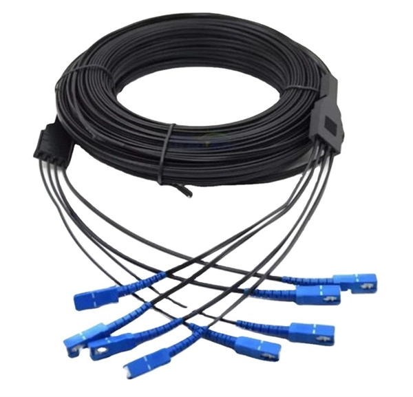
Loss of a 1 2 Optical Splitter
5 dB depending on splitter type. Optional: patch panels, attenuators, or extra components. Helps cover dirt, aging, and measurement tolerances. Common values: 2, 4, 8, 16, 32, 64. Excess loss accounts for manufacturing imperfections, typically 0. DISCLAIMER: These calculators are provided for. Optical splitters, encompassing FBT (Fused Biconical Taper) couplers and PLC (Planar Lightwave Circuit) splitters, are prevalent passive optical devices designed to divide fiber optic light into multiple segments based on a specified ratio. Understanding the types of splitters, their impact on network performance, and how to measure their losses ensures high-quality network operation and facilitates optimal splitter selection based on. In fiber optic networks, particularly in FTTx (Fiber to the x) and PON (Passive Optical Networks) deployments, splitters play a central role in distributing the optical signal from a single source to multiple destinations.
[PDF Version]
-
What can be done about low luminosity in the tail fiber Can it be cured
Out of date adhesives may not cure properly and/or have low strength bonds between the fiber and the ferrule. Before you get started, set up your work space. It's best to work on a black mat because it helps you see the fiber. Or it could be caused by the quality of the connector itself, such as poor end-face geometry that doesn't pass the parameters defined by IEC PAS 61755-3 standards, including angle of the polish, fiber height, radius of curvature or apex offset. A more common cause is poor field termination that. Fiber optic networks are celebrated for their speed and reliability, but even the best systems can encounter problems. When issues like signal loss, slow speeds, or intermittent connectivity arise, systematic troubleshooting is key. Measured in decibels (dB), loss degrades signal quality, limits distance, increases bit-error rate, and escalates infrastructure cost. High-quality single mode fiber will often exhibit attenuation (loss of power) as low as 0.
[PDF Version]
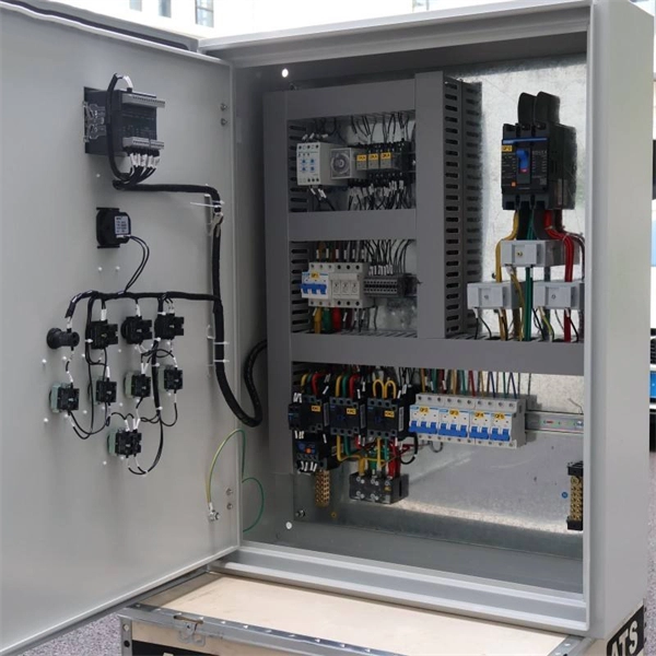
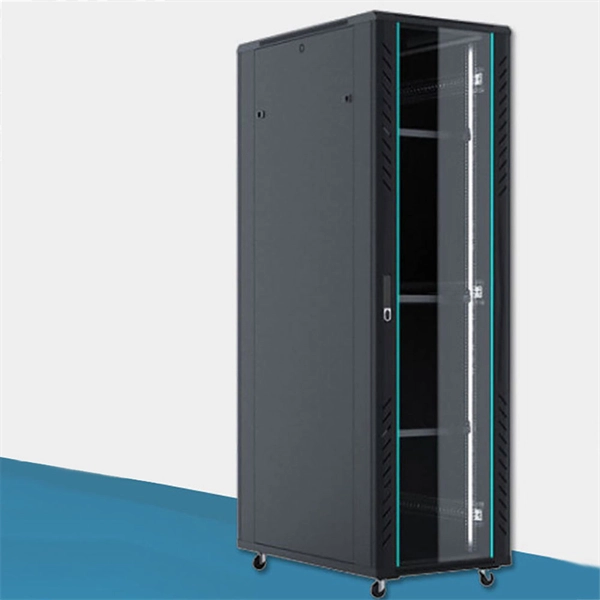
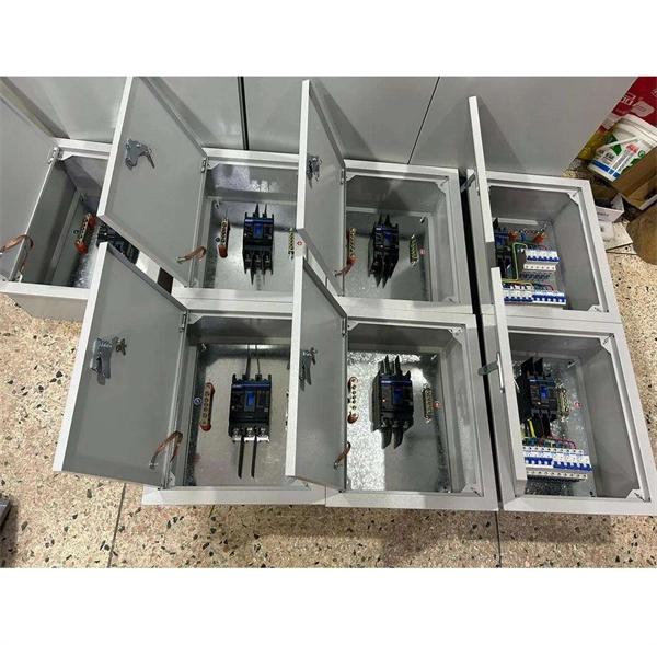
Telecom Racks & Cabinets
19-inch racks, wall-mount cabinets, open frames with high load capacity and seismic rating.
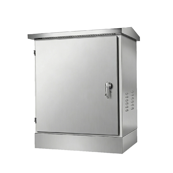
Outdoor Climate Cabinets
IP55/IP66 outdoor enclosures with integrated cooling/heating, -40°C to +55°C operation.
Smart PDUs & Power Distribution
Intelligent PDUs with remote monitoring, per-outlet switching, and environmental sensors.
Shelters & Network Cabinets
Prefabricated telecom shelters, emergency comms shelters, and network cabinets with cable management.