-
Price for secondary wiring of high voltage switchgear
This switchgear estimator helps to estimate the total cost of installing switchgear panels. Follow the steps below: Enter the number of panels you intend to install. Costs for building or upgrading a electrical substation vary widely based on size, voltage, and equipment. Major drivers include transformer size, switchgear, protection systems, land and permitting, and labor. All material cost is populated. Each piece of equipment is given more than one (1) type. These products are backed by the technological expertise of ABB's centres of excellence across infrastructure markets through a wide manufacturing and marketing network.
[PDF Version]
-
What is the principle behind high and low light power meters
Most power meters are based on the principle of a thermal detector: optical power is converted to heating power in some absorber structure with a black coating, and the resulting temperature rise (or actually the temperature difference between the absorber and the mount) is. Most power meters are based on the principle of a thermal detector: optical power is converted to heating power in some absorber structure with a black coating, and the resulting temperature rise (or actually the temperature difference between the absorber and the mount) is. An optical power meter (or laser powermeter) is an instrument for the measurement of the optical power (the delivered energy per unit time) in a light beam, for example a laser beam. Typically, it allows for power measurements only with a relatively low bandwidth, and will display, for example. An optical power meter (OPM) is a device used to measure the power in an optical signal. An OPM uses a photodiode to generate an electrical current proportional to optical power.
[PDF Version]
-
What are the effects of high power consumption in optical modules
The high power consumption of optical modules not only increases operating costs but also limits the integration and sustainability of optical modules. Other external factors, such as operating temperature, network load fluctuations, cooling systems, and power management, can affect the performance and power consumption of optical modules. Reducing the power draw of thousands of transceivers directly translates to lower electricity bills. This article delves into the world of energy efficient fiber modules, examining their technical specifications, real-world. AI workloads, combined with other traffic, are putting immense pressure on networks — not just for bandwidth, but also for power and space, resources that don't scale linearly with data demand, given constraints in electrical supply, cooling and rack and aisle space. 5. As data rates continue to surge past 800G and into multi-terabit speeds, energy efficiency is becoming a critical concern for network operators, hyperscalers, and AI computing environments.
[PDF Version]
-
Power Fiber Optic Cable Unlocking Procedure
This guide outlines proper methods to safely remove fiber optic cable from modems in your home or office. As an experienced technology writer who has covered broadband advancements for over a decade, I aim to provide readers with trustworthy instructions endorsed by industry. The Fiber Optic Association, Inc. (FOA) was founded in 1995 to help develop the workforce to build the fiber optic networks to support a rapid expansion in communications and the Internet. The charter of the FOA was to promote professionalism in fiber optics through education, certification, and. Unplugging a fiber optic cable from a modem is a task that requires careful handling to avoid damaging the delicate fibers within the cable. Fiber optic cables are different from traditional copper cables, as they use light to transmit data, and the connectors are more sensitive. Whether you are building a data center, upgrading campus infrastructure, or expanding a telecom backbone, SFP modules enable rapid deployment and easy upgrades.
[PDF Version]
-
Requirements for main power lines in computer room distribution boxes
Installation Requirements: Proper conductor sizing, overcurrent protection, and grounding in accordance with local electrical codes. Professional electrical installation is essential for safety, code compliance, and optimal performance. Article 645 of the National Electrical Code provides specific requirements that must be met before the rules in Article 645 can be applied to an IT room. These include the following (in. Each rack must safely deliver stable electrical power to dozens of servers, switches, and storage devices while maintaining reliability, airflow efficiency, and electrical safety. A relatively common method is a classification of data centres by numbers. Optimizing server room power layout is crucial for ensuring efficiency and reliability. As such, maintaining consistent uptime is a must. This area is climate-controlled and equipped with advanced security.
[PDF Version]
-
Distance between communication optical cables and power cables
The National Electrical Code establishes specific minimum distances when communications cables must run near power and light circuits. This practice is mandatory for two distinct reasons: ensuring the safety of the structure and its occupants, and preserving the integrity of sensitive data. TECHNICAL GUIDELINE July 30, 2020 TG030 Rev. The electrical energy of the power cables can. Maintaining proper separation between power, data, and limited energy cabling is foundational to system performance, safety, and code compliance. Separation isn't just an EMI precaution — it protects signaling, reduces rework, and ensures pathways meet inspection expectations across risers. How much separation is required between communications cables and power cords? Issue: There is a concern that power cords can interfere with signal integrity in data cables if they're installed too closely. Environment: All versions and serial ranges. Cause: Data cables and power cords are. Surprisingly, there isn't a one-size-fits-all answer. 47 (B), it says that the direct buried conductive fiber optic cable shall be 12 in (300 mm) away from the power cables.
[PDF Version]
-
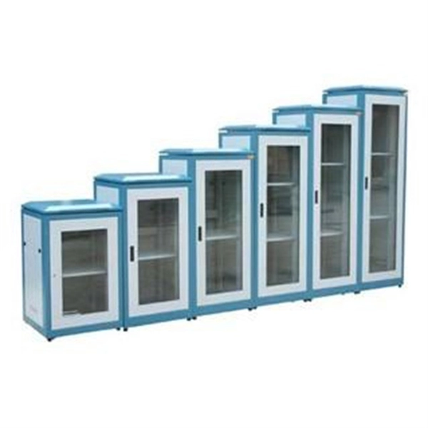
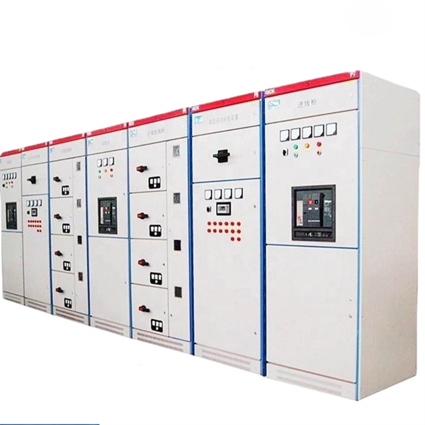
Specifications and Models of Distribution Boxes at Nanya Power Plant
Home / blog / Ultimate Guide to Distribution Boxes (DB Boxes): Types, Components, Applications, and How to Choose the Right OneHome / blog / Ultimate Guide to Distribution Boxes (DB Boxes): Types, Components, Applications, and How to Choose the Right OneLow voltage cabinet produced in cooperation with SCHNIDER company, compliant with IEC 61439-2 and GB7251. 12 standards for low voltage distribution cabinets. Independent unit room compartments, MCCB live parts are covered with insulating plates, ensuring good operational safety. Low-voltage fixed switchgear GGD series: Mainly used in power industries such as substations and power plants, with high breaking. What is a Distribution Box? A distribution box, or DB box, is a circuit breaker enclosure. The hub distributes electrical power from a single input source to various circuits throughout a building.
[PDF Version]
-
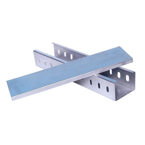
Cable tray installation at the Iranian power plant
Whether you're building a commercial setup or upgrading an industrial plant, proper cable tray installation ensures neat wiring, safe access, and easy maintenance. This guide breaks down the process step by step. Below is the detailed cable tray installation method statement not only for cable tray but also applicable for GI ladder and trunking for indoor and outdoor applications and in service rooms like pump rooms, electrical rooms and plant rooms etc. The method gives details of how the work will be carried out and what health and safety issues and controls that. er on wall and existing metal support Fastening the MS Suppor x 1. 6 mm thickness and complete with high tensile bolt, washers and nuts.
[PDF Version]
-
How to open an integrated power socket
Insert a plug into the outlet partway. The outlet will loosen as the plastic surrounding the prongs is slightly. This story shows how to remove and replace a soldered-in integrated circuit with an IC socket. How to snip out and remove an integrated circuit from a pcb and install an. How to open and close and use 3 Pins Terminals Panel Female 16A and 10A 250V AC Inline Adapter Plug Power Socket Connectors DIY Power Supply Electronic. The board's dimensions match the medium-sized add-on board as defined in the mikroBUS specification. Through use of. A socket is a device that provides a connection point for electrical components, allowing for easy insertion and removal of plugs or connectors. Sockets are widely used in electronics to facilitate modularity, ease of maintenance, and quick replacement of components.
[PDF Version]
-
Characteristics of AC DC Integrated Power Supplies
Modern industrial AC-DC designs often require: Higher efficiency through soft-switching techniques and fast-switching GaN devices. Lower THD over wide load conditions using power factor correction. This chapter discusses fundamental topics including the idea of a power supply, characteristics and functions of AC and DC power supplies, and the construction and operation of AC/DC power sources. The current must be supplied in a controlled manner — and with an accurate voltage — to a wide range of loads, sometimes simultaneously, all without lett ne chargers, or internal, such as in larger devices gulated. With increased reliability and outstanding performance, Infineon's CoolSET™ AC-DC integrated power stages are designed to offer additional protection to increase system robustness. Reinforced Insulation is provided between primary & secondary circuits AVAILABLE NOW! is the NXT-1000 – 1000 Watt AC-DC Single Output Power Supply! Click here to read more. When selecting an AC-DC power supply, the primary consideration is determining the system power requirements. The user should verify the AC input voltage range of the power supply is compatible with their target markets and.
[PDF Version]
-
Power Consumption Comparison of Bending-Insensitive Fiber Optic OM5
Bending losses are influenced by different optical parameters like Mode Field Diameter (MFD), Cut-off wavelength and MAC value. This paper highlights the results of a series of tests conducted, to determine the power loss of matched clad step index Single Mode Optical . G. 657 standard but are optimized for different bend radius tolerances and deployment constraints. A1 fibers serve. led globally, compared with just 200 million kilometres in 2010. Optical cabling systems need to ofer faster, more reliable and cost-efective deployment methods in. Fiber coatings and cables are designed to prevent as much bending loss as possible, but it's part of the nature of the fiber design. 652, which describes its characteristics, has been adapted to this experience. B3 might seem like a subtle decision. Data center scale grows rapidly and.
[PDF Version]
-
Calculation of Power Imbalance on 10kV Busbar
Choose to calculate by Current (Amps) or Power (kW). Enter your system's parameters (e. Select the busbar Material (Copper or Aluminum). A wider or thicker bar has lower resistance, so loss falls. Natural convection removes less heat than forced airflow. Because both resistance and cooling change with. Calculate current capacity, voltage drop, and temperature rise for electrical bus bars. This calculator helps electrical engineers, panel builders, and power system designers to properly size and evaluate bus bars.
[PDF Version]
-
Communication power system connection map
An interactive map from National Public Radio visualizes the U. electric grid through transmission lines, sources of power, power plants. Open map of the world's electricity, telecoms, oil, and gas infrastructure, using data from OpenStreetMap. This comprehensive web-based mapping tool provides real-time visualization of high-voltage transmission lines, substations, and power distribution networks across the United. Infrastructure mapping is all about creating a detailed blueprint of physical and organizational structures. Environmental Protection. World's high voltage power grid above 200 kV in 2023.
[PDF Version]
-
How to use the intelligent module in the power distribution box
The IPDM E/R is an intelligent power distribution module that helps manage the electrical system in your vehicle. This manual provides instructions for inspecting the power and ground circuits of the IPDM E/R, as well as instructions for removing and installing the IPDM E/R. Fuse and Fusible Link Arrangement HR ENGINE AND MR ENGINE WITH CVT DIESEL ENGINE AND MR ENGINE WITH M/T. LHD LHD : How To Read Harness Layout CONNECTOR SYMBOL Main symbols of connector (in Harness Layout) are indicated in the below. IPDM E/R (INTELLIGENT. In this video I show the steps and procedures I use to properly diagnose a bad IPDM And a bad engine relay. more. IPDM E/R integrated relays are not serviceable parts, and must not be removed from the unit. Do not use a unit which has been dropped. REMOVAL Disconnect the negative battery terminal. Refer to Removal and Installation. If you missed. Precaution for Supplemental Restraint System (SRS) "AIR BAG" and "SEAT BELT PRE-TENSIONER" The Supplemental Restraint System such as "AIR BAG" and "SEAT BELT PRE-TENSIONER",.
[PDF Version]
-
How to ground cable trays in a power distribution room
This comprehensive guide delves into the complexities of cable tray grounding, offering in-depth insights into its importance, principles, design considerations, installation best practices, and maintenance requirements. These systems provide an efficient and adaptable solution for managing a wide range of cables, including power cables, control cables, Ethernet, and fiber optic lines. 8, 11, and 12, and the National Electrical Code Sections 318-3-© and 318-7. It is also covered in NEMA Standard VE-2. The purpose of power grounding (Article 250) is to minimize the damage from wiring or. Cable tray grounding is an indispensable aspect of electrical installations that plays a pivotal role in ensuring safety, reliability, and efficiency. It involves connecting cable trays to the facility's grounding system, providing a low-impedance path for fault currents and protecting personnel. When setting up electrical systems, grounding is a must. The Cable Tray Grounding Wire ensures everything runs safely and smoothly. The metal in cable trays may be used as the EGC as per the limitations.
[PDF Version]
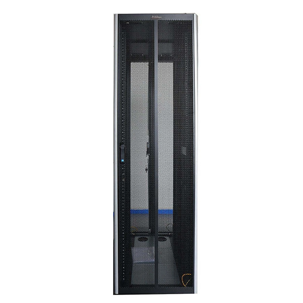
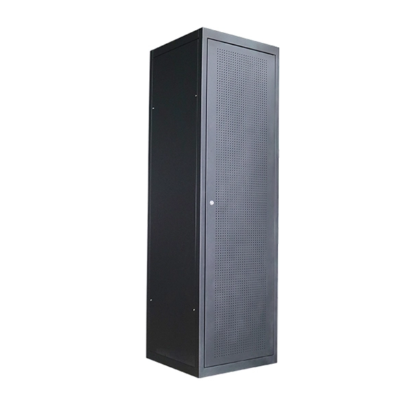
Telecom Racks & Cabinets
19-inch racks, wall-mount cabinets, open frames with high load capacity and seismic rating.
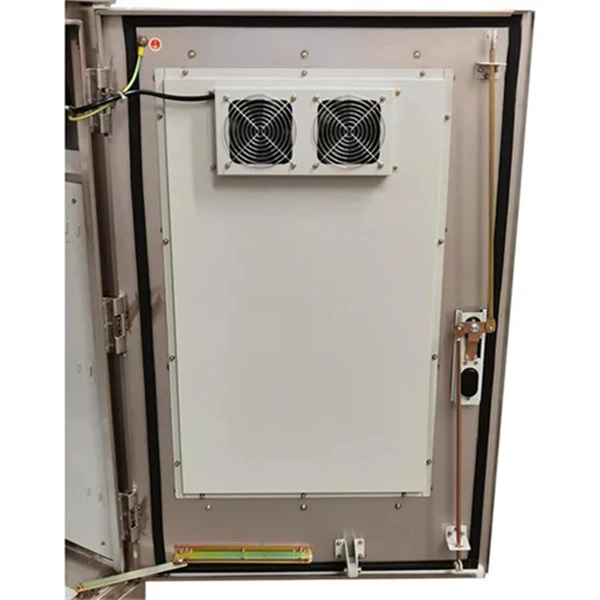
Outdoor Climate Cabinets
IP55/IP66 outdoor enclosures with integrated cooling/heating, -40°C to +55°C operation.
Smart PDUs & Power Distribution
Intelligent PDUs with remote monitoring, per-outlet switching, and environmental sensors.
Shelters & Network Cabinets
Prefabricated telecom shelters, emergency comms shelters, and network cabinets with cable management.