-
How to calculate the input power formula for an optical power meter
Calculation Example: This calculator determines the received optical power (in dBm) by first converting the input power from milliwatts (mW) to dBm using the formula: P_in_dBm = 10 * log10 (P_in_mW). TIA standard test FOTP-95 covers the measurement of optical power. It can be a focusing power, also called dioptric power, for example of a lens or microscope objective.
[PDF Version]
-
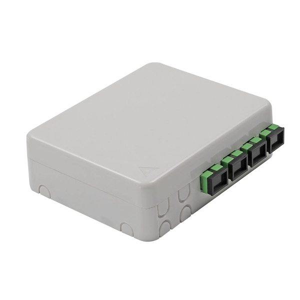
How to calculate the cost of splicing junction boxes for optical cables
At $60-120/hr, a fusion splice in a drop location will cost $30-$60 labor plus the splicing cost. Even less expensive than that is using pre-terminated fiber cable. Adtell Integration is capable of supporting your fusion splicing requirements whether they require Singlemode, Multimode, or Ribbon Splicing. We use. The cost of splicing fiber optic cables can vary significantly based on several factors, including the type of splice, the equipment used, the location of the job, and the expertise required. Understanding these factors can help businesses and individuals budget effectively for fiber optic. Furnished with four plugged cable ports (2 aluminum and 2 plastic) for either All-Dielectric Self-Supporting (ADSS) or Optical Ground Wire (OPGW) cables, the splice enclosure can be pre-mounted to a structure before completion of the splicing phase. 80% of costs for an FTTP deployment go to labor. Fiber splice closures are.
[PDF Version]
-
How to use an optical power meter with multimode fiber optic cable
To use a power meter for fiber optic testing, always clean connectors first with lint-free wipes or click-to-clean tools. Select the correct wavelength and set your reference. You measure optical power in dBm or insertion loss in dB. Consistent procedures ensure accuracy. Links to videos and more. This device is widely used by technicians and engineers to measure the power level of optical signals and ensure network performance meets required standards. Here's how they work: A power.
[PDF Version]
-
How to calibrate a BG-301A optical power meter
Once connected, turn on the optical power meter and let it warm up for a couple of minutes. Next, set your optical power meter to the color and power of the light. Finding ways to optimize the performance of test equipment is one of the primary issues for managers, yet maintaining a large inventory of test and measurement equipment requires a systematic and efficient approach. This makes regular calibration of test and measurement equipment one of the most. Imagine having to deal with cells of various shapes and colors (your colorimeter) that will mislead you about light as long as you don't decide for the real measure at good-scale (your holometer) calibrated. Select. We can calibrate your Fiber Optic Power Meters at two service price levels: ISO9001 or ISO/ IEC 17025 We check the cleanliness of the optical detector. If we find a performance problem with the received instrument, we will let you know. This paper describes the measurement standards, techniques, systems, and.
[PDF Version]
-
How to interpret a laboratory optical power meter
To use a power meter for fiber optic testing, always clean connectors first with lint-free wipes or click-to-clean tools. Select the correct wavelength and set your reference. You measure optical power in dBm or insertion loss in dB. It's very useful in many jobs, especially in communications, fiber optics, andelectronics. All of our surgical devices and whether they are working correctly and producing the appropriate amount. An optical power meter (OPM) is a device used to measure the power in an optical signal. Typically both transmitters and receivers have receptacles for fiber optic connectors, so measuring the. We describe the results of a comparison of reference standards between the National Institute of Standards and Technology (NIST, USA) and Laboratorio de Metrología, Instituto Costarricense de Electricidad (LAMETRO-ICE, Costa Rica) for optical fiber–based power measurements at wavelengths of 1310.
[PDF Version]
-
How to calculate the transmission speed of a 4-core optical fiber cable
This calculator determines the bits per second that can be transmitted through a multimode fiber cable, given its bandwidth. Key Parameters: • Center Diameter, Fiber Diameter, Packing Efficiency, Section Count Calculation: Visualization: • Color-coded radial diagram with per-section. RP Fiber Calculator is a highly convenient software for doing various calculations on optical fibers with radially symmetric refractive index profiles. It has an intuitive graphical user interface with tabs for the following purposes: Your browser does not support the video tag. The configuration and results can be exported as PDF. You can also select components to configure connections below and add the field configuration below it. The components will show. A 500 MHz·km fiber can transmit 500 MHz optical signals over 1 kilometer, or 250 MHz over 2 kilometers, demonstrating the inverse relationship between bandwidth and distance. 792 meters per microsecond (µs) or 3.
[PDF Version]
-
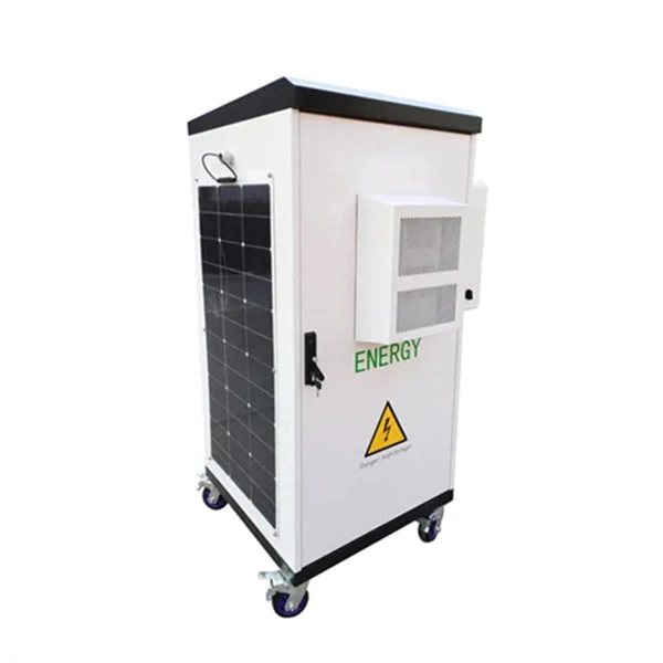
How to ground an industrial power distribution box
Attach a ground wire from one of the threaded studs (A) at the bottom of the housing, to the mounting plate (B). The ground resistance between all system parts shall be <. Power from factory ground must be installed by a qualified electrician. Each DISTRIBUTION BOX and controller must be grounded. 26 mm 2 (10 AWG) ground wire must be used, and in all other markets a 6 mm 2 must be used. Grounding of the units: Attach a ground wire from one of. Whether you're designing a new facility, upgrading existing infrastructure, or ensuring ongoing compliance, mastering industrial electrical grounding requirements protects your workforce, prevents costly downtime, and keeps your operation running safely. The National Electric Code (NEC), Article 250, contains specific requirements on the grounding of electrical power systems and equipment. The recommended practices in this document are intended to provide explanations of how electrical systems operate. While these guidelines apply to the majority of.
[PDF Version]
-
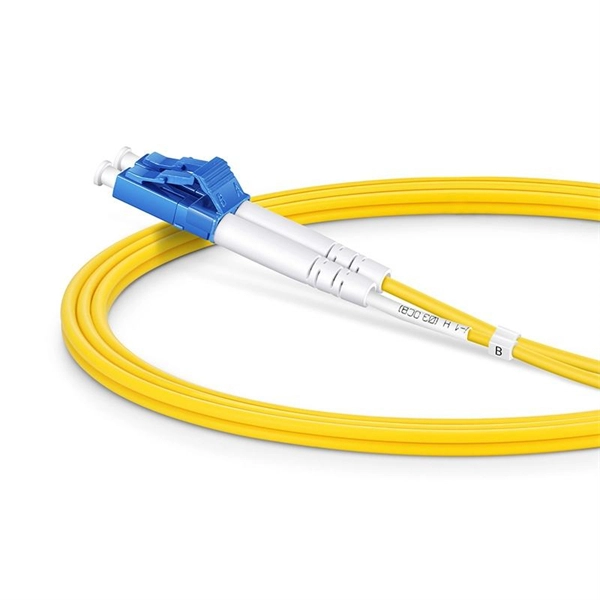
How to connect an optical power meter to an optical fiber
Disconnect the reference cable from the meter and connect it to the fiber link under test. This value shows the total insertion loss. Tip: The one-jumper method includes losses at both ends, simulating. An optical power meter measures the strength of light traveling through a fiber optic cable, giving you a reading in dBm (decibels relative to one milliwatt). All are written in the same straightforward format: what equipment do you need, what are the procedures for testing, options in implementing the test, measurement errors and documenting the results. Consistent procedures ensure accuracy. Verify light travels from. Below are general answers on how to operate, maintain, and calibrate an optical fiber ranger from the list of GAO Tek's optical power meters.
[PDF Version]
-
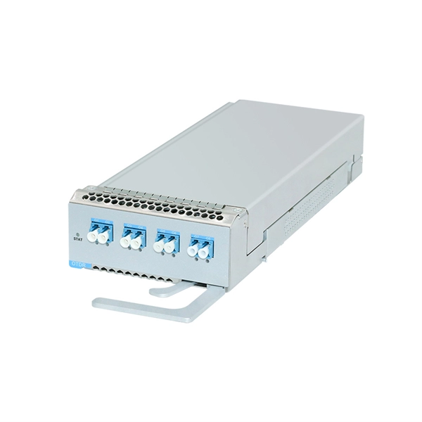
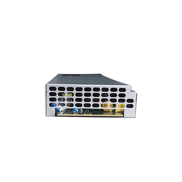
How to Use Industrial Long-Distance Optical Modules
Use this ordered checklist to avoid rework and minimize downtime. Distance and fiber type: confirm MMF vs SMF, and whether you have OM3, OM4, or OS2. Don't rely on “rated reach” alone; compute link budget with patch cords and splices. A long-distance optical module is an optical module with a transmission distance of more than 30km. What Are Long-Distance SFP Modules? SFP (Small Form-factor Pluggable) modules are standardized network transceivers that. How to Use 10G SFP+ Long-distance SFP Module? There are many kinds of 10G SFP + optical transceivers in the market, some optical transceivers can transmit 80km, and some others can transmit 100km, even 120km. Do you know the reason why the transmission distance is different? And why the. Optimizing Attenuation in Long-Distance Optical Modules: A Key to Reliable Fiber Communication In optical fiber communication, the attenuation operation for long-distance modules is a critical process to ensure system stability. As automation systems evolve toward distributed architectures and smart factories, high-speed and long-distance communication between PLC modules.
[PDF Version]
-
How to connect the power composite optical cable
Here is a detailed step-by-step guide on how to install the composite fiber optic cable. Before you begin it's essential to take into account the distance and route the cable will need to travel. The composite fiber optic cable is a type of cable that combines both fiber optic and copper conductors within a single cable sheath. Power+™ composite cables utilize fiber optic strands to provide the link to the network and a pair of stranded copper. In this video, we'll walk you through everything you need to know about composite fiber optic cables, from installation best practices to their versatile applications.
[PDF Version]
-
How is the G7 optical power meter
With its high-definition color screen, 9 wavelength support, USB charging, and intelligent features, this portable meter is perfect for telecommunications technicians, network installers, and fiber optic professionals who require accurate measurements in the field. The G7 Optical Power Meter is a professional-grade, compact fiber optic testing device featuring an integrated design with bright surface finish and hidden detector. This gives you the best flexibility for any range of fiber optic power measurement. Its color LCD screen provides clear and easy-to-read results, allowing users to quickly analyze and interpret test data.
[PDF Version]
-
How to solve the problem of an inaccurate optical power meter
When working with automated power meters, you'll need to verify both linearity factor and input optical conditions that can introduce power accuracy issues. Your calibration process should address average power measurements with documented measurement uncertainty values. A send"'optical power meter is correctly calibrated when using a equivalent testing practices. Below are general answers on how to operate, maintain, and calibrate an optical fiber ranger from the list of GAO Tek's optical power meters. Power On: Ensure the device is charged or properly connected to a power source. Ephraim Greenfield The total accuracy of measurement of a laser power/energy meter is affected by the following factors: The calibration¹ uncertainty of the measuring sensor. Fluctuating optical power often results in: Common root causes include connector contamination, bending loss, or poor mechanical contact. Low power or unstable OSNR forces Forward Error Correction to work harder.
[PDF Version]
-
How to use the China Unicom optical power meter
To use a power meter for fiber optic testing, always clean connectors first with lint-free wipes or click-to-clean tools. Select the correct wavelength and set your reference. Consistent procedures ensure. REF/dB key: Short press the dB to switch unit, click once nW/dBm/dB to enter the upper clear data, press and hold until REF is displayed on the screen, and set the current optical power as reference value, enter the relative optical power test mode, the screen will display the setted reference. View & download of more than 188 UNICOM PDF user manuals, service manuals, operating guides. Consistent procedures ensure accuracy. Verify light travels from. Introduction Introduction The UNICOM III probe is a portable optical (infrared) communications device that transfers digital information between Elster electronic meters, EMF registers, and other reader/ programmer equipment. Two basic configurations of probes are available: one is compatible with. Zhejiang TriBrer Optical Power Meter might help you assess the power is optical watts (W) and decibels (dB).
[PDF Version]
-
How to calculate the impedance value of a 35KV busbar in a power station
This guide explains the engineering logic behind busbar impedance calculation in a practical and readable manner. It covers core theory, design factors, simplified formulas, and examples that reflect real-world power system work. The aim is to provide a clear technical reference that supports. Line impedance consists of resistance (R), inductive reactance (X), and sometimes capacitive reactance (C) components, but typically R and X dominate for overhead and underground lines. The tables below show common. Step-by-step technique which proceeds branch by branch. Busbar Calculations: This calculator uses standard formulas to calculate the resistance, voltage drop, and power loss in a rectangular busbar. Resistivity is. kVA base, IB base current (A) and ZB base impedance (Ω) are given by following equations: Now that the base parameters are defined let's see how the per unit parameters are defined: If the impedance is desired in actual ohms, the following formula can be used: To convert short circuit current to. The paper presents an analytical method for calculating impedances of rectangular bus ducts. The results of resistances and.
[PDF Version]
-
How to splice optical cables in a photovoltaic power station
In this guide, we'll walk you through the entire process of preparing fiber optic cable for splicing and termination to fiber connectors. We'll explore the necessary tools, safety precautions, and step-by-step procedures for cable connectors, mechanical and fusion. The focus of this article is the testing associated with in-place cables, connectors, and splices for AC and DC cables in utility-scale solar applications and USA-based standards organizations. American Clean Power (ACP) is the primary trade association for alternative energy in the USA. The. Use of standard grades of plastic wire ties is by far the most common method used by installers to support and secure direct current (DC) string wiring in an array. Regardless of the type of fiber network you're deploying, be it for telecom, enterprise data centers, or smart city infrastructure, fusion splicing provides the benefits of. Imagine your photovoltaic panel array as a giant robot - the optical cables are its nerves, transmitting critical data faster than you can say "sunburn. " Mess up these welds, and suddenly your smart solar farm becomes about as communicative as a rock.
[PDF Version]
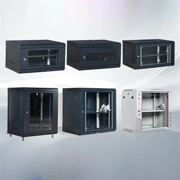
Telecom Racks & Cabinets
19-inch racks, wall-mount cabinets, open frames with high load capacity and seismic rating.
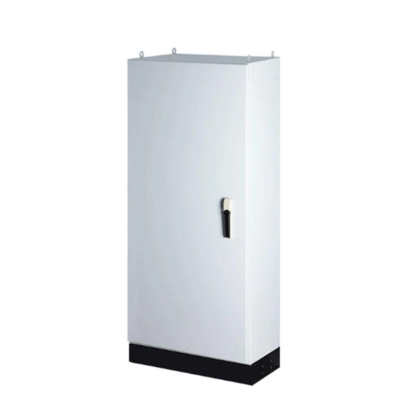
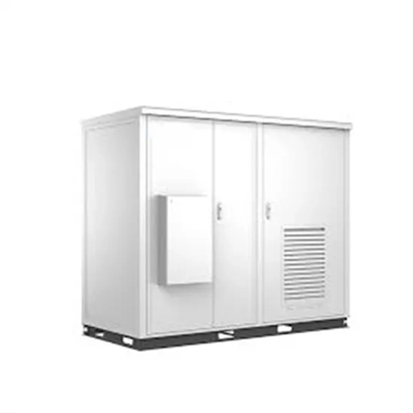
Outdoor Climate Cabinets
IP55/IP66 outdoor enclosures with integrated cooling/heating, -40°C to +55°C operation.
Smart PDUs & Power Distribution
Intelligent PDUs with remote monitoring, per-outlet switching, and environmental sensors.
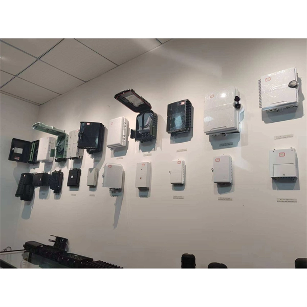
Shelters & Network Cabinets
Prefabricated telecom shelters, emergency comms shelters, and network cabinets with cable management.