-
How to select the number of optical fiber cores
The number of optical cores in an optical fiber is the total number of equipment interfaces multiplied by 2, plus 10% to 20% of the spare quantity, and if the communication mode of the equipment has serial communication and equipment multiplexing, you can reduce the number of cores. This article will walk you through the basics of fiber optic cores and provide practical guidance for selecting the suitable fiber optic cable to meet your networking needs. Made from either high-quality. Fiber optic cables consist of multiple thin strands of glass or plastic, known as “cores. ” These cores carry the data signals via light. The number of. Common fiber cores include 1 core, 2 cores, 6 cores, 8 cores, etc.
[PDF Version]
-

How to select the number of optical cores in a fiber optic cable
The number of optical cores in an optical fiber is the total number of equipment interfaces multiplied by 2, plus 10% to 20% of the spare quantity, and if the communication mode of the equipment has serial communication and equipment multiplexing, you can reduce the number of cores. Fiber cores are the heart of fiber optic cables, transmitting light signals that carry data. Made from either high-quality glass or plastic, the core plays a critical role in determining the cable's performance.
[PDF Version]
-
How many cores are ideal for a telecommunications fiber optic cable
Multi-core fiber optic cables can contain 3 to 12 cores within a single cable. This significantly increases the data transmission rate, making them ideal for modern, high-demand applications. Understanding Fiber Cores: Core: The central glass fiber that transmits light signals. The number of cores you choose directly impacts the capacity and. The number of optical cores in an optical fiber is the total number of equipment interfaces multiplied by 2, plus 10% to 20% of the spare quantity, and if the communication mode of the equipment has serial communication and equipment multiplexing, you can reduce the number of cores. The number of. When planning outdoor fiber networks—whether for duct installations, aerial deployments, or direct burial—one critical question arises: How many cores does a GYTA cable offer? As a staple loose-tube armored fiber optic cable, GYTA is celebrated for its flexibility in core counts, tailored to. Fiber cores are the central components of fiber optic cables, responsible for transmitting light signals that carry data.
[PDF Version]
-
Number of fiber optic connector cores
Multimode fiber optic cables can have multiple cores, commonly 2 or 4. The number of cores refers to the individual strands within the cable that carry the optical signals. These cores allow for the transmission of multiple signals simultaneously, increasing the capacity and. The number of optical cores in an optical fiber is the total number of equipment interfaces multiplied by 2, plus 10% to 20% of the spare quantity, and if the communication mode of the equipment has serial communication and equipment multiplexing, you can reduce the number of cores. Made from either high-quality. At TARLUZ, we understand that selecting the right fiber core count is critical for network performance, scalability, and cost-effectiveness. They are typically made of high-quality glass.
[PDF Version]
-
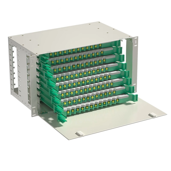
How to configure the number of ports on a fiber optic patch panel
Here's a step-by-step guide to help you properly arrange fiber optic patch panels in a data center environment. Before installation, assess your network's current and future needs: Use this information to select the appropriate patch panel type—rack-mounted, wall-mounted, or modular high-density. Fiber patch panels come in various configurations, including 12-port, 24-port, 48-port, 72-port, 96-port, and 144-port fiber distribution frames. These options cater to different network requirements and capacities. The most common configurations are 24 port fiber patch panel and 48 port fiber. ● The patch panel is a long-term solution that can provide high-density port connectivity solutions for 4x10 Gbps, 100 Gbps, 2x100 Gbps, 4x100 Gbps, 400 Gbps, 2x400 Gbps, and 4x400 Gbps breakout requirements. And label the ports to identify different cables so that technicians have clear instructions on what they need. Suitable to SC LC FC ST or other fiber connectors as requested, Meanwhile, 12, 24, 36, 48, 72, 96, 144 ports are available Mounted directly onto walls for space-saving installations.
[PDF Version]
-
How to Choose a Fiber Optic Cable Identifier in Greece
Use color coding for fiber types to quickly identify cables. Yellow indicates single-mode fiber, while orange and aqua mark multimode fibers. Follow TIA-606-B standards for labeling. With clear tables and updated details, it serves as a comprehensive reference for technicians handling modern fiber optic installations. By adopting the TIA/EIA‑598C standard, you gain a universal “language” of colors that speeds identification, reduces miswiring, and enhances safety across cable jackets, connectors, buffer tubes, and splice trays. You rely on these color systems to ensure correct fiber routing, splicing accuracy, tube identification, polarity. Have you ever wondered how the installers can identify every single fiber in a cable with hundreds of fibers? Well, this would be impossible without a standardized system. Since fibers are tiny (about 250 µm in diameter), number marking, or other printed markings is not practical.
[PDF Version]
-
How many fiber optic cores can a single optical module connect to
A simple rule is that each device needs two cores—one for sending and one for receiving data. Start by counting how many devices you're connecting. (actually use a four core optical cable) This is because apart from one-core optical fiber, there are basically no optical cables with an odd number of cores, such as three-core, five-core, etc. It is worth. The total number of cores for a 1pc fiber patch cable is calculated as the number of branches multiplied by the number of cores per branch (if there are no branches, the number of branches = 1). In the context of accelerating digitalization, the rational. o In optical modules, "core" refers to the light-transmitting channel in the fiber.
[PDF Version]
-
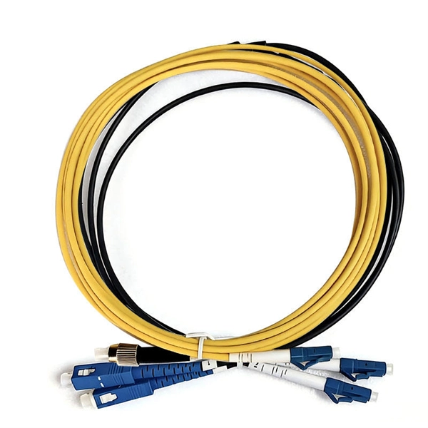
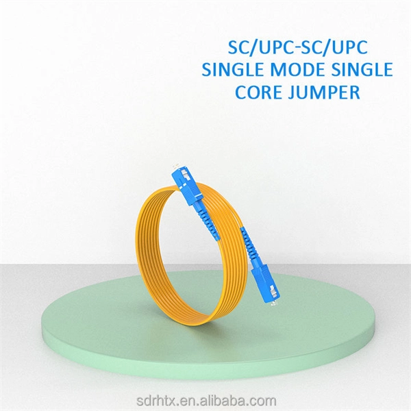
How many fiber optic cores does a fiber optic patch cord contain
Multi-core patch cords are fiber assemblies containing multiple fibers within a single cable jacket, typically available in 4, 6, 12, and 24-fiber configurations. These assemblies are widely used in ODN distribution frames, data center racks, MDU risers, and fiber management systems where higher. Fiber cores are the heart of fiber optic cables, transmitting light signals that carry data. Made from either high-quality glass or plastic, the core plays a critical role in determining the cable's performance. Fiber optic patch cords (also known as fiber optic connectors) are fiber optic cables fitted with connector plugs at both ends, which are used to achieve the optical path. Connecting fiber optic cables to patch panels may seem like a straightforward task, but improper connections can lead to signal loss, decreased network efficiency, and even costly repairs. That's why understanding the proper techniques and tools for this process is essential.
[PDF Version]
-
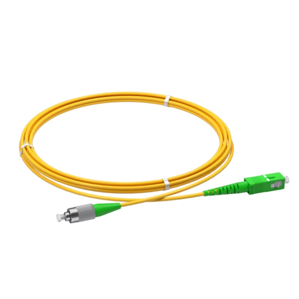
How to tell the front from the back of a fiber optic patch cord
The ferrule end face of the patch cord is ground into different structures. PC, APC, and UPC are three different ferrule polishing methods, representing the structural differences of the front face of the ceramic ferrule. As shown below, the ferrule is the housing for the bare end of an optical. At ZION Communication, we design and manufacture a full range of fiber patch cords for: This guide will help you quickly understand the main types of fiber patch cords and how to choose the right solution for your project – and how ZION can support you with stable quality, flexible customization. Here at Fiber Optic Center, we believe it's important to introduce engineers and technicians to various aspects of the production process to manufacture high-performance, world-class fiber optic cable assemblies. Ideally, your finished fiber optic cable assembly will meet all relevant international. Fiber optic patch cords, also known as fiber optic patch cables or fiber jumpers, are indispensable components in modern optical networks. Fiber optic patch cables are found almost everywhere; cable television networks (CATV), data centers, computer networks, and telephone networks.
[PDF Version]
-
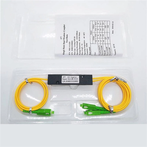
How many fiber cores should a fiber optic splitter connect to
A simple rule is that each device needs two cores—one for sending and one for receiving data. This guide focuses on two critical aspects of optical splitters that define FTTH performance: split ratios (how signals are divided) and splitting architectures (how splitters are deployed). By understanding these elements, network operators can design PON (Passive Optical Network) systems that. The total number of cores for a 1pc fiber patch cable is calculated as the number of branches multiplied by the number of cores per branch (if there are no branches, the number of branches = 1). For example, the total number of cores in an MTP®-8 trunk cable equals 4 (number of branches) x 8 (MTP-8. The number of optical cores in an optical fiber is the total number of equipment interfaces multiplied by 2, plus 10% to 20% of the spare quantity, and if the communication mode of the equipment has serial communication and equipment multiplexing, you can reduce the number of cores. As XGS-PON continues to be adopted, some service.
[PDF Version]
-
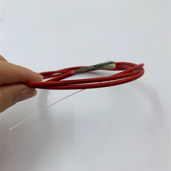
How to separate the fiber cores of OPGW24-core optical cable
Removing the aluminum strands and outer layers of the OPGW cable exposes the fiber optic cores 7, which is essential for proper termination. Use a file to smooth any sharp edges after removing the aluminum strands 8. Carefully separate the metal loose tubes without damaging. Proper termination of OPGW cables involves precise steps like careful handling 3, removing outer layers, cleaning fibers, and securing with clamps. In the construction of electric power dedicated communication network, the number of optical fibers used is usually 12 to 24 cores. With the continuous expansion of system capacity according to new business requirements, the number of cores is gradually increasing, and individual line sections have. out this step, cut a small piece of pipe, about 2 feet, from the free end of the cable and practice cuttin of the cable. While holding the cable, pull the optical units completely out of the pipe by pullin toward the tower. What is Fiber Optic Splicing and Why is it Needed? – #1. First, a heat-shrink tube is placed over the OPGW cable.
[PDF Version]
-
How to calculate the number of ports on a fiber optic patch panel
The fundamental calculation formula is: Total patch cords = Total number of device ports × Connection factor Where the connection factor depends on the connection method: 2. Scenario-Based Calculations The redundancy factor is typically 0 (no redundancy) or 1 (1:1 redundancy). Premium-Line 19” Rack mountable fiber optic patch panel is designed for both patching and splicing, accepts whole range of adapters including SC, ST, FC, LC adapters. 2 * Rear cable entries accommodate cables with diameter below 10mm. These options cater to different network requirements and capacities. Network architects and procurement managers must now evaluate patch panels not merely. Follow TIA-942 or ISO/IEC 11801 standards for structured cabling. It is important to know the.
[PDF Version]
-
How to calculate the number of pigtails in a fiber distribution box
This guide explains how to evaluate fiber termination box capacity correctly, including fiber count, port configuration, splitter accommodation, and future growth. Many buyers assume “capacity” simply means the number of adapter ports on the front panel (for example, 8 ports or 16 ports). In. A fiber optic pigtail is a short, usually unjacketed, optical fiber cable that has a factory-installed connector on one end and a length of exposed fiber at the other. The connector end can be linked directly to network equipment, while the exposed end can be spliced to another fiber optic cable. Thus, a fiber termination box is used to terminate the optical fiber. Fiber termination box (FTB), also known as optical terminal box (OTB), generally refers to a distribution box specially designed for fiber cable management (fiber patch cables/pigtails) in FTTH applications. The ODF consists of a metal housing, cable entry ports.
[PDF Version]
-
How to install a fiber optic distribution box
In this tutorial, we're diving into the installation process of Optic Fiber Terminal/Distribution Box. Whether you're a beginner or an. The optical fiber distribution box allows people to easily access the optical fibers in the box, and can well protect the optical fibers. In addition, the drawer structure also facilitates high-density wiring and good cable management. Familiarize yourself to understand the unit's placement in your network.
[PDF Version]
-
How to install an optical fiber connector box
This guide walks you through the complete fiber installation process, from checking availability to optimizing your Wi-Fi network performance. But how does fiber internet installation actually bring connectivity from a national backbone into your home? The process involves a combination of national infrastructure, local engineering, and property-level setup. Aerial Service Drop: A cable coming from a pole to your house, connected at a small box called an. Dgtl Infra provides an in-depth overview of the fiber optic cable installation process, which involves a fiber drop, fiber splicing, mounting a “wall box” or termination enclosure, enabling fiber to enter the home, setting-up an optical network terminal (ONT), and activating internet, video, and. Follow along as we take you through the step-by-step process of installing fiber internet! From preparing the site to connecting the final cables, we'll show you what goes into bringing high-speed internet to your doorstep. Whether you're a tech enthusiast or just curious about how it all w.
[PDF Version]
Telecom Racks & Cabinets
19-inch racks, wall-mount cabinets, open frames with high load capacity and seismic rating.
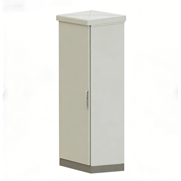
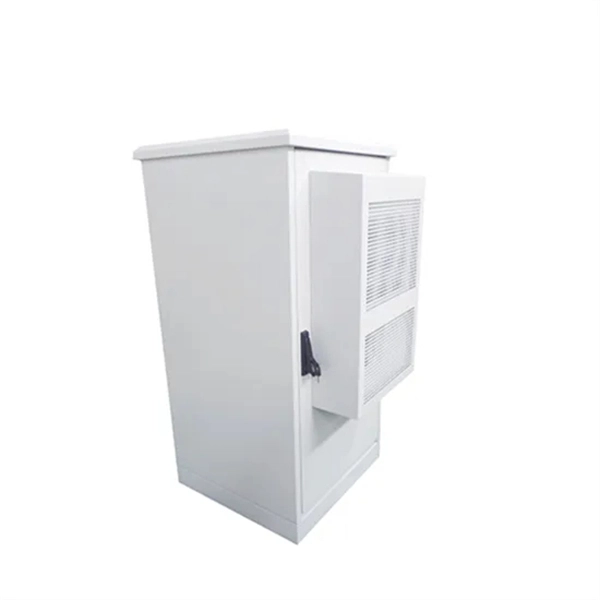
Outdoor Climate Cabinets
IP55/IP66 outdoor enclosures with integrated cooling/heating, -40°C to +55°C operation.
Smart PDUs & Power Distribution
Intelligent PDUs with remote monitoring, per-outlet switching, and environmental sensors.
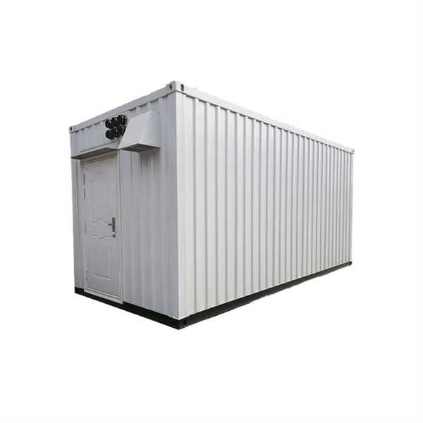
Shelters & Network Cabinets
Prefabricated telecom shelters, emergency comms shelters, and network cabinets with cable management.