-
How to make right-angle bends in a mesh cable tray
Cut out a V-shape from the side wires, then bend the basket at the cut to form your angle. Reinforce with couplers or brackets if needed. What's the best way to support modified baskets? Use compatible support arms, drop rods, or wall brackets, especially at junctions or. Unlike perforated trays, bends can be created directly at site without expensive fittings. This guide explains how to make 90° bends, vertical bends, tees, and offsets in wire mesh cable trays safely and professionally. Horizontal 90° Bend (Flat Bend) 2. When a wire cable tray is cut, the fact that a. Learn how to make a 90 degree bend using the RAD T90 Kit. [Choose “Wire Basket Component Calculator” from the Resources/ Links drop down menu on www. Follow along to mark, cut, file, and bend the tray to perfection! #electriciansoftiktok #electrician #sparky #howto #tutorial #tips Keywords: 90-degree bend cable tray, bending cable tray tutorial.
[PDF Version]
-
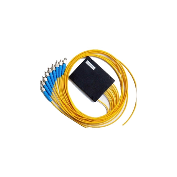
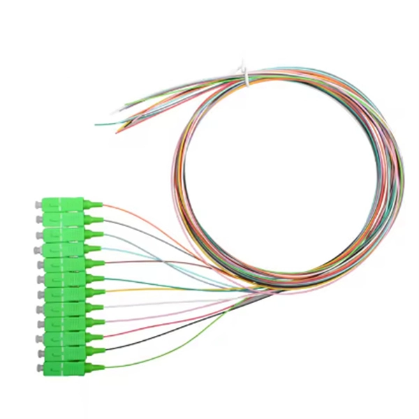
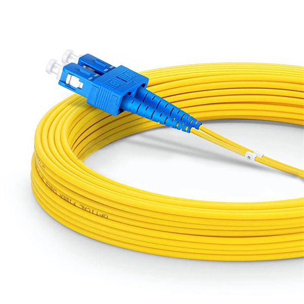
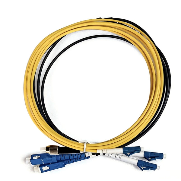
How to tell the front from the back of a fiber optic patch cord
The ferrule end face of the patch cord is ground into different structures. PC, APC, and UPC are three different ferrule polishing methods, representing the structural differences of the front face of the ceramic ferrule. As shown below, the ferrule is the housing for the bare end of an optical. At ZION Communication, we design and manufacture a full range of fiber patch cords for: This guide will help you quickly understand the main types of fiber patch cords and how to choose the right solution for your project – and how ZION can support you with stable quality, flexible customization. Here at Fiber Optic Center, we believe it's important to introduce engineers and technicians to various aspects of the production process to manufacture high-performance, world-class fiber optic cable assemblies. Ideally, your finished fiber optic cable assembly will meet all relevant international. Fiber optic patch cords, also known as fiber optic patch cables or fiber jumpers, are indispensable components in modern optical networks. Fiber optic patch cables are found almost everywhere; cable television networks (CATV), data centers, computer networks, and telephone networks.
[PDF Version]
-
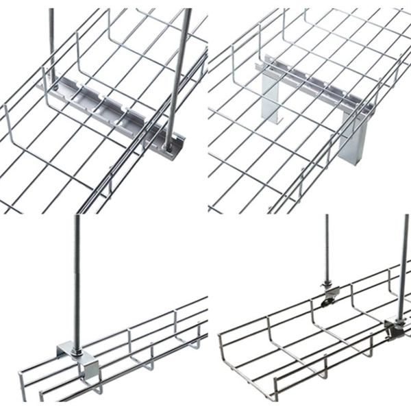
How to install a wire mesh cable tray machine
Whether you're working on an industrial, commercial, or data center project, this step-by-step guide will help you get it done safely and efficiently. 🔧 What You'll Learn: Preparing the installation area and measuring for accuracy Installing mounting brackets and ensuring proper. Wire mesh cable trays provide an excellent solution for managing and organizing cables efficiently. In this complete installation guide, we'll walk you through the process of installing wire mesh cable trays step-by-step, complete with images to illustrate each stage What is a Wire Mesh Cable Tray?In this video, we'll walk you through the entire process of installing a wire mesh cable tray system, from preparation to completion. 🔧 What You'll. For detailed information about the product, please visit our website: https://link. Qualified field personnel working to a. en completely installed, without damage either to conductors or structural system use maintain spacing or to keep cables in place when the tray is ect the minimum bend ra-dius for cables as they exit the bottom of the cable tray. A rung spacing of 6 to 9 inches (150 to 230 mm) is preferable when.
[PDF Version]
-
How to model a mesh cable tray in UG
A cable tray system is ideal for protecting and organizing electrical connections in commercial and industrial environments. This article offers a straightforward, step-by-step method for creating one. 3D Warehouse is a website of searchable, pre-made 3D models that works seamlessly with SketchUp. Connect your model to generate a building LCA directly from Revit and understand the impact of choosing one material over another. com Design App Load BIM objects straight into Revit in 1 click. in the manufacturer libraries Legrand CabloCAD, TkRem etc. This command allows to draw single trays or automatic drawing of tray sequences with simultaneously insertion of elbows. Discover all CAD files of the "Cable trays" category from Supplier-Certified Catalogs ✅ SOLIDWORKS, Inventor, Creo, CATIA, Solid Edge, autoCAD, Revit and many more CAD software but also as STEP, STL, IGES, STL, DWG, DXF and more neutral CAD formats. Cable trays are necessary for safe and effective cable management in various settings, including.
[PDF Version]
-
How many mesh cable tray manufacturers are there in Honduras
Find Honduras Mesh manufacturers & suppliers with shipment details on Trademo. Access global exporters database and gain exporter insights. Subscribe to global trade data intelligence to discover new business. 594 Electrical,Wire,Cable suppliers in Honduras shipped to 1,057 buyers worldwide. Sourcing managers and procurement leaders use Volza's Company Profiler to analyze shipment volumes, trade routes, and buyer distribution—helping. If you are searching for reliable Cable Tray Manufacturing Unit manufacturers in COUNTRY, VyaaparOne offers a structured and verified B2B platform to simplify your sourcing process. We believe in building fruitful business partnerships. Every buyer chooses. Keep your cables safe and organized with our high-quality cable trays. Cable Trays are important for ensuring the protection of the wiring system and supporting insulated electric cables used for distribution and communication.
[PDF Version]
-
Quotation for Dutch Mesh Cable Tray Crossarms
Please complete the form below to request a Cable Tray quote. I agree to be informed regularly about Eaton products, promotions and news. Cable tray crossarms are key load-bearing components in cable tray systems, used to support cables, fix the cable tray body, or adjust the laying spacing. We designs and manufactures cable tray systems, including perforated tray, cable ladder, channel tray and strut (metal framing), Combining local manufacture and distribution with an extensive product range, these facilities ensure we can effectively support customer demand and respond rapidly to. MP Husky is a founding member of the USA Cable Tray Institute and the leader in US cable tray systems and cable support systems.
[PDF Version]
-
How to configure IP on an access switch
This article provides instructions on how to configure the IP address settings of your switch through the Command Line Interface (CLI). If you are unfamiliar with terms in this document, check out Cisco Business: Glossary of New Terms. The IP address of the switch can be manually configured or automatically received from a Dynamic Host Configuration Protocol (DHCP) server. This means that you can buy a Cisco switch, plug in the right cables to connect various devices to the switch, power it on, and the switch will work properly. An IOS is a Cisco proprietary operating system. It includes thousands of commands for various tasks.
[PDF Version]
-
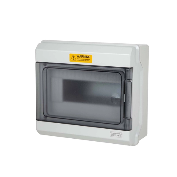
What is the name of the door wire of a three-level distribution box
The neutral wire (white) from the main disconnect terminates at a neutral busbar. The National Electrical Code (NEC) provides comprehensive safety standards for electrical installations, including requirements for electrical panels (main service panels and subpanels or breaker box). NEC Article 408. They are the conductors between the terminals of the service equipment and the service drop, overhead service conductors, service lateral, or underground service conductors. An overhead power connection from the utility. A distribution board (also known as panelboard, circuit breaker panel, breaker panel, circuit breaker, electric panel, fuse box or DB box) is a component of an electricity supply system that divides an electrical power feed into subsidiary circuits while providing a protective fuse or circuit. Distribution boards, often referred to as electrical panels or breaker boxes, serve as the nerve center of any electrical system. Three-phase distribution boards are used in large factories, buildings, manufacturing units.
[PDF Version]
-
Wiring on the side of the distribution box
Wiring Direction: Wiring between the main circuit breaker and each branch circuit breaker in the box generally goes on the left, and the wiring out of the distribution box generally goes on the right. Binding Requirements: The wires should be bound with. Learn how to wire a distribution box step by step! This video shows real on-site footage of electrical installation, demonstrating safe and standardized wiring methods used by professionals. It takes the incoming power and safely distributes it to different circuits throughout your building. 2 kV on the primary side and step it down to 120V single-phase and 120/240V split-phase for residential applications.
[PDF Version]
-
How to configure a switch for fiber optic cable
Connect the fiber optic cable: Attach the fiber optic cable's connector to the transceiver module on the switch. Make sure the connector type (e. If you're looking to learn how to configure fiber optics on a Cisco switch, it's important to first configure the switch settings so it's ready for fiber optics. The information in this document is based on all Catalyst 9000 Series switches. This includes Doppler. However, setting up a fiber optic connection to your router can seem daunting if you're unfamiliar with the process. Why Use Fiber Optic Internet? Before diving into the setup, let's quickly. Fiber optic cabling is increasingly used to connect network switches and other datacom equipment, especially in long-distance and mission-critical applications. SFP modules insert into these slots and and require two strands of fiber, typically duplex Using multi mode fiber (for runs under 1000.
[PDF Version]
-
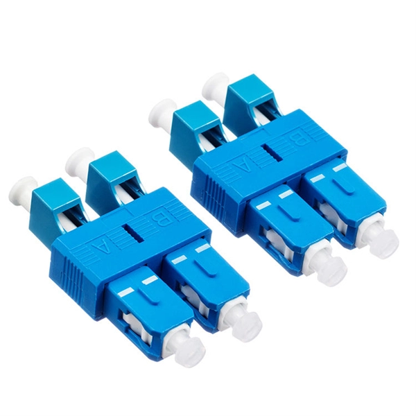
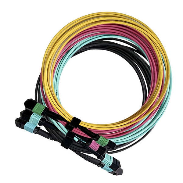
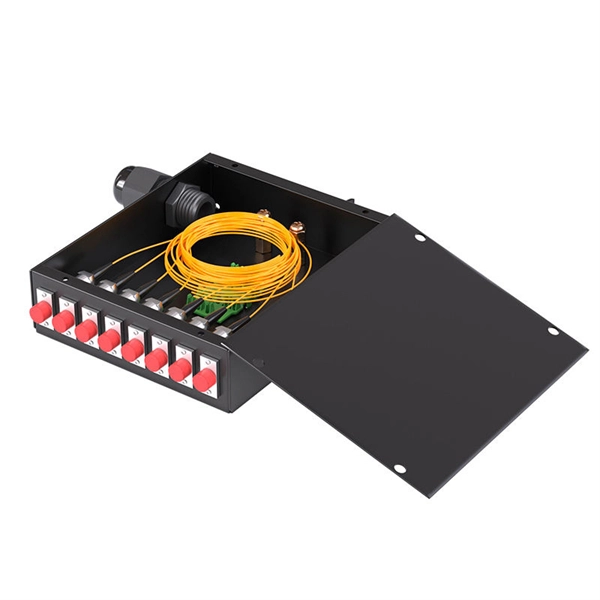
How to configure the number of ports on a fiber optic patch panel
Here's a step-by-step guide to help you properly arrange fiber optic patch panels in a data center environment. Before installation, assess your network's current and future needs: Use this information to select the appropriate patch panel type—rack-mounted, wall-mounted, or modular high-density. Fiber patch panels come in various configurations, including 12-port, 24-port, 48-port, 72-port, 96-port, and 144-port fiber distribution frames. These options cater to different network requirements and capacities. The most common configurations are 24 port fiber patch panel and 48 port fiber. ● The patch panel is a long-term solution that can provide high-density port connectivity solutions for 4x10 Gbps, 100 Gbps, 2x100 Gbps, 4x100 Gbps, 400 Gbps, 2x400 Gbps, and 4x400 Gbps breakout requirements. And label the ports to identify different cables so that technicians have clear instructions on what they need. Suitable to SC LC FC ST or other fiber connectors as requested, Meanwhile, 12, 24, 36, 48, 72, 96, 144 ports are available Mounted directly onto walls for space-saving installations.
[PDF Version]
-
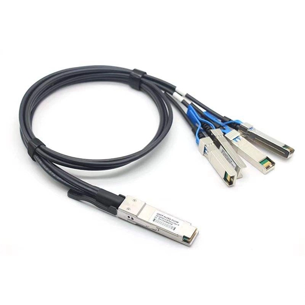
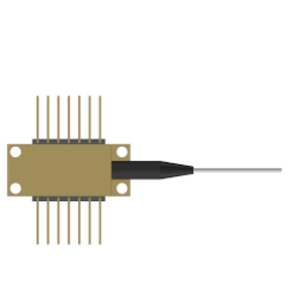
How to configure a fiber optic transceiver switch
This quick yet practical demonstration dives into the installation, configuration, and traffic monitoring of SFP optical and twisted-pair transceivers. SFP Transceiver Module – Choose the appropriate module based on your network requirements (e. If you're looking to learn how to configure fiber optics on a Cisco switch, it's important to first configure the switch settings so it's ready for fiber optics. These transceiver modules are hot-swappable input/output (I/O) devices that plug into 100BASE, 1000BASE and 10GBASE ports (for SFP+), which connect the module. A newly added feature on some Microchip Gigabit Ethernet switches is a serial Gigabit media independent interface (SGMII) for one of the ports.
[PDF Version]
-
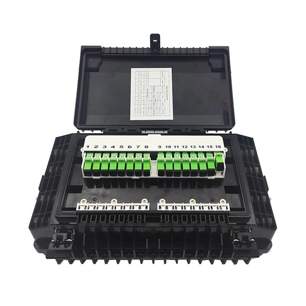
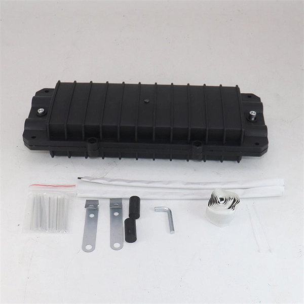
How to configure a fiber optic terminal box as an end
Learn how to install a fiber optic termination box step-by-step for FTTH projects. Covers mounting, splicing, routing, labeling, and testing for indoor/outdoor use. Installing a fiber optic termination box is one of those jobs that looks simple on paper, but it's. The fiber termination box is an interface between the fiber cable from the line side and the pigtails to be passed to the fiber distribution frame. A fiber pigtail is a specific hardware connection used for cable termination. It functions as a junction between the incoming fiber cable and the outgoing customer-side fiber cable, where one fiber can be spliced, patched. Fiber Termination Boxes (FTBs) are crucial components in fiber optic networks, facilitating the termination, connection, and management of optical fibers. Proper installation and maintenance of FTBs are essential to ensure the reliability and performance of the network infrastructure. It serves as a termination point for optical fibers, providing a secure and organized space for connecting and managing fiber optic cables. FTBs play a vital role in ensuring the.
[PDF Version]
-
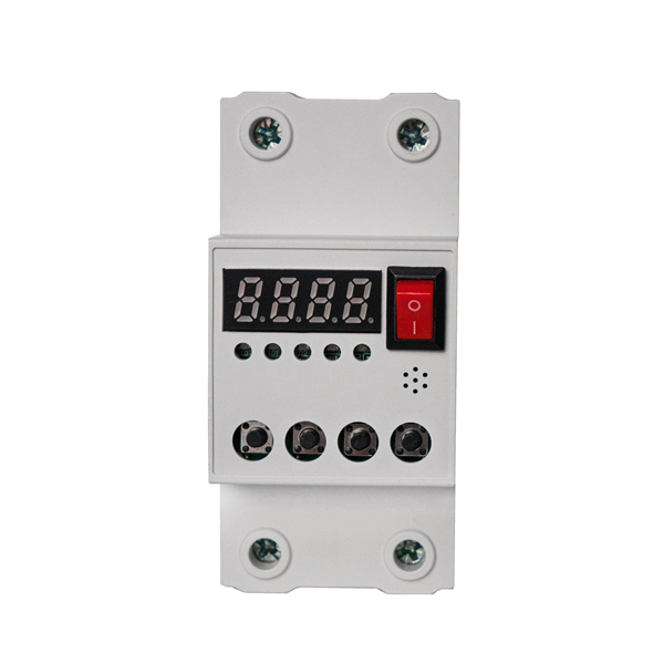
How to configure relay protection time limit
The time delay of zone 2 and zone 3 elements should be set to coordinate with time-step protection at both the remote and local buses. This allows time for the remote zone 1 element to pick up, plus breaker operating time. Plug Setting Multiplier (PSM) indicates how many times the determined relay secondary current (typically the CT secondary) exceeds the relay pickup (plug) current. It is the key quantity utilized in IDMT. Use this Protection Relay Setting Calculator to calculate pickup current, time multiplier settings (TMS), operating time, coordination time interval (CTI), and plug setting multiplier (PSM) using fault current, CT ratio, and IEC 60255 curve parameters. These calculations are critical in industrial. To configure protective devices such as making a relay setting, having all the consideration of the fault severity and decision-making time, it is important to know parameters, rules, and protection zone so that the reliability of the power system having continuous supply, is not compromised. set to clear. Distance relays measure impedance (Z = V/I) to detect faults.
[PDF Version]
-
Is it okay to use cable trays without mesh
Right off the bat, there's no universal “better” option. Whether a wire mesh basket or a cable tray is the best fit depends on your installation environment, cable type, and budget. Perforated trays stand out by providing airflow, providing added protection — more than wire mesh trays. Wire mesh trays are widely considered easy-to-install cable trays. Three families dominate most projects— ladder, perforated, and wire mesh. One of the most common questions from users is: “A cable tray is a cable tray—why are there so many types?” The answer is simple: different cable. Cable tray systems provide a safe, organized, and flexible method for supporting insulated conductors and cables in commercial and industrial electrical installations. When properly selected and installed, cable trays simplify routing, improve accessibility, and support future expansion while. In instrumentation EPC (Engineering, Procurement, and Construction) projects, installing cable trays is very important for making sure that signals are sent reliably, that people are safe, and that systems work well for a long time.
[PDF Version]
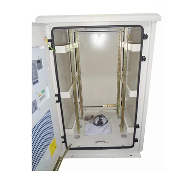
Telecom Racks & Cabinets
19-inch racks, wall-mount cabinets, open frames with high load capacity and seismic rating.
Outdoor Climate Cabinets
IP55/IP66 outdoor enclosures with integrated cooling/heating, -40°C to +55°C operation.
Smart PDUs & Power Distribution
Intelligent PDUs with remote monitoring, per-outlet switching, and environmental sensors.
Shelters & Network Cabinets
Prefabricated telecom shelters, emergency comms shelters, and network cabinets with cable management.