-
Complete List of Optical Fiber Cable Materials with Image
Each optical cable is constructed using a precise combination of optical fibers, strength members, buffer tubes, water-blocking elements, armoring, and protective jackets. Here is the extended technical table of all raw materials used in the fiber optic cable industry. ■ The Five Key Parts of a Fiber Optic Cable A fiber optic cable is composed of five core elements: Every hardware component has a specific function for proper signal transfer, construction resilience, and environmental defense. The choice of material is an engineering decision driven by the need to. Understanding the Core: The Heart of Fiber Optics The Cladding: A Critical Component for Containment Protective Coating: The First Defense Against the World Strength Members: Backbone of Fiber Optic Cables The Outer Jacket: A Shield Against the Elements Getting Flexible: Bend Insensitive Fibers A. A: PVC (polyvinyl chloride) is a widely used jacket material that provides good mechanical protection for fiber optic cables. PVC is fire-resistant but can release toxic fumes when burned.
[PDF Version]
-
Standard models of polarization-maintaining optical fiber
Different types of polarization-maintaning fibers are designed depending on the geometry of the stress elements: “PANDA“ fibers, “Bow-Tie“ fibers or “Oval-Inner Clad“ fibers. Image of the cross section of a polarization-maintaining optical fiber patch cord, taken with an illuminated microscopic viewer called a fiberscope. The two small, eye-like circles are the stress rods and the tiny circle between them is the core. Corning offers the broadest portfolio of PANDA PM fibers from wavelengths of 400-1550 nm and designs such as High NA and Flame Retardant coatings. It provides an expert-curated supplier directory, buyer-focused technical background information, and structured selection criteria to support professional procurement decisions. Its core principle is to utilize highly birefringent structures (such as stress zones or geometric asymmetry) to. In this article, the latest in FOC's series covering specialty fibers and their fabrication, we discuss polarization-maintaining (PM) fibers and the various approaches used to make them.
[PDF Version]
-
Standard Requirements for Underground Burial of Communication Optical Fiber Cables
While local codes and soil conditions dictate specific requirements, general industry guidelines are: Standard Residential/Commercial Areas: 24 to 36 inches (60 to 90 cm) deep. Under Roadways or Driveways: 36 to 48 inches (90 to 120 cm) deep, often within a conduit for added. Underground fiber optic cable installation follows specific standards that govern burial depth, testing methods, installation techniques, and safety requirements. These standards, established by organizations like the National Electrical Code (NEC), National Electrical Safety Code (NESC), and. Estimate minimum burial depth (cover) for underground electrical, fiber, and low-voltage cable runs using a practical, code-aware ruleset. Use this page to plan trench depth, compare conduit options, and prepare for inspection conversations. 2 meters (3-4 feet) deep to reduce the likelihood of accidentally being dug up. However, simply hitting this depth isn't enough to guarantee your network survives.
[PDF Version]
-
High-precision UAE active optical fiber for local area networks
We supply premium fiber optic cables, splicing equipment, testing instruments, and provide professional installation services across Dubai, Abu Dhabi, Ajman and the entire UAE region. NAFICON is a fiber industry expert with over 30 years of manufacturing legacy. Naficon Liitin Oy, the parent company based out of Finland is one of the most trusted suppliers for telecom, data centers and utility across Northern Europe. It is built upon precise engineering and regulatory standards that ensure operational efficiency and service continuity under all. Fusion Tech Solutions (FTS) is a UAE-based fiber optic and telecommunications company specializing in FTTH (Fiber to the Home), network infrastructure, and data center solutions. Our fiber services support secure communication, dependable data transfer, and scalable connectivity across commercial and industrial. United Arab Emirates (UAE) Active Optical Cable (aoc) Assemblies Professional Market Global Outlook, Country Deep-Dives & Strategic Opportunities (2024-2033) Market size (2024): USD 1. 2 billion · Forecast (2033): 3. As autonomous vehicles, smart grids, and sensor-based systems scale, the demand for ultra-fast.
[PDF Version]
-
620nm optical energy transmission using multimode fiber
Here we demonstrate petabit-per-second-class data transmission using a space-division multiplexing fiber that approaches the limits of spatial multiplexing whilst minimizing the required signal processing complexity. ClearCurve multimode laser-optimized, bend resilient fibers are widely deployed to deliver high data rate, low latency transmission. As the inventor of bend-insensitive optical fiber, Corning ensures quality and reliability by measuring key attributes, including effective modal bandwidth on every. Multimode fibers (MMF) are an example of a highly scattering medium which scramble the coherent light propagating within them and produce seemingly random patterns. High-power lasers. The increasing demand for transmission capacity in fiber-optic communications makes multimode fibers (MMFs) attractive by enabling simultaneous multi-channel data transmission. However, inherent mode crosstalk among transmission channels limits its applicability. This is done by designing and fabricating a low-loss 19-core multi-core fiber with.
[PDF Version]
-
Formula for calculating the length of optical fiber in optical cables
The Fiber Length formula is defined as the length of fiber cable that is being used to propagate the signal and is represented as L = Vg*Td or Length of Fiber = Group Velocity*Group Delay. Optical fiber length is typically measured using a technique that involves timing how long it takes for light to travel through the fiber. Specifically, the VOLT utilizes a round-robin method to accurately determine the length of optical fiber cables. There are four ways to calculate the cable length. Group Velocity - (Measured in Meter per Second) - Group Velocity is the velocity with which the overall envelope shape of the wave's amplitudes; known as the modulation. The length of pitch of this spiral screw line. A tool that computes how many fibers fit in a circular bundle and splits them into user-defined segments for cable-assembly planning. Key Parameters: • Center Diameter, Fiber Diameter, Packing Efficiency, Section Count Calculation: Visualization: • Color-coded radial diagram with per-section.
[PDF Version]
-
What materials are optical fiber fusion splices made of
Arc fusion splicing is an established method for joining optical fibres in communication networks, ensuring splice loss down to 0. 05 dB and excellent reliability. Telecom fibres are covered by IEC 60793 and ITU-T G. 657 standards, with common material (fused silica) and. Optical fiber fusion splicing is the process by which a permanent, low-loss, high-strength, welded joint is formed between two optical fibers. The Relevance Inspector will open in the Coveo Administration Console. Selected products added to your list. Your query couldn't be sent to the following URL: https://levitonmanufacturing. The goal is to fuse the two fibers together in such a way that light passing through the fibers is not scattered or reflected back by the splice, and so that the splice and the region surrounding it are almost as strong as the. NASA has explored laser-fused fiber splicing as a future technology for orbital communication relays. Fusion splicing uses an electric arc to melt and fuse two fiber cores – often made of ultra-pure glass about 9 microns.
[PDF Version]
-
Fiber Attenuation Standards for Optical Cables
IEC 60793-1-40:2024 establishes uniform requirements for measuring the attenuation of optical fibre, thereby assisting in the inspection of fibres and cables for commercial purposes. This article explains eight of the most important global fiber and cable standards — ITU-T, IEC, TIA, ISO/IEC, and Telcordia — covering their scope, applications, and why they matter in. Listing of all FOA standards FOA Standard FOA-1: Testing Loss of Installed Fiber Optic Cable Plant, (Insertion Loss, TIA OFSTP-14, OFSTP-7, ISO/IEC 61280, ISO/IEC 14763, etc. ) More FOA Standard FOA-2: Testing Loss of Fiber Optic Cables, Single Ended, (Insertion Loss, TIA FOTP-171, OFSTP-7,. This document outlines the specifications for a single-mode optical fiber and cable designed for use around the 1310 nm zero-dispersion wavelength, suitable for both the 1310 nm and 1550 nm regions, and compatible with analogue and digital transmission. Four methods are described for measuring attenuation, one being that for modelling spectral attenuation: -method D:. ic system. Corning recommends that all fiber optic systems be tested to a minimum set.
[PDF Version]
-
No optical fiber input to the fiber optic cable
Many fiber internet problems come from dirty connectors or loose plugs, not major faults. Power cycling or restarting your ONT (Optical Network Terminal) often resolves simple troubleshooting internet issues. However, like any technology, issues may arise, leading to anxiety and frustration when your optical cable isn't. Problems within a fiber link can occur due to a wide variety of reasons. Or it could be caused by the quality of the connector itself, such as poor end-face geometry that doesn't pass the. When your fiber optic network stops working, begin with a structured approach. Power. Fiber optic troubleshooting is an essential skill for network administrators, technicians, and engineers responsible for maintaining and repairing fiber optic systems. Why Use Fiber Optic Internet? Before diving into the setup, let's quickly recap why fiber optics are worth the effort: Lightning-fast speeds (up to 1 Gbps or higher).
[PDF Version]
-
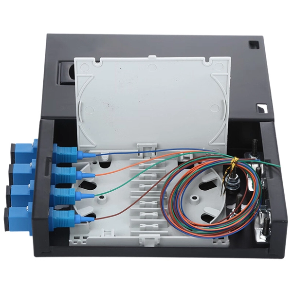
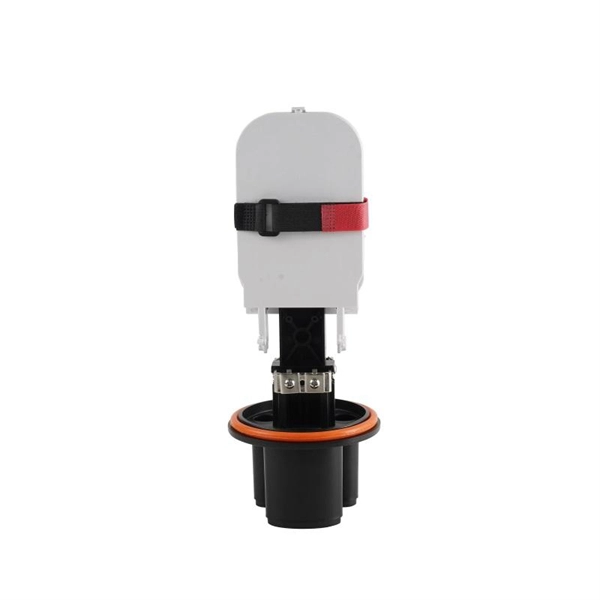
How to install an optical fiber connector box
This guide walks you through the complete fiber installation process, from checking availability to optimizing your Wi-Fi network performance. But how does fiber internet installation actually bring connectivity from a national backbone into your home? The process involves a combination of national infrastructure, local engineering, and property-level setup. Aerial Service Drop: A cable coming from a pole to your house, connected at a small box called an. Dgtl Infra provides an in-depth overview of the fiber optic cable installation process, which involves a fiber drop, fiber splicing, mounting a “wall box” or termination enclosure, enabling fiber to enter the home, setting-up an optical network terminal (ONT), and activating internet, video, and. Follow along as we take you through the step-by-step process of installing fiber internet! From preparing the site to connecting the final cables, we'll show you what goes into bringing high-speed internet to your doorstep. Whether you're a tech enthusiast or just curious about how it all w.
[PDF Version]
-
Methods for Detecting Optical Fiber Routes
Effective fiber testing utilizes advanced tools such as Optical Loss Test Sets (OLTS), Optical Time-Domain Reflectometers (OTDR), and Visual Fault Locators (VFL) to diagnose and correct issues, ensuring optimal network performance. This paper provides a detailed overview of the fault detection techniques in optical fiber network with a background examining the types of faults as perceived by local monitoring centers known as Network Operations Centers. Such a comprehensive approach to fiber optic cable testing. Optical fiber networks are engineered for high capacity, long reach, and low latency, but their operational value depends on visibility. Without continuous monitoring, outages may be discovered only after end users notice performance degradation. You use it to find the exact.
[PDF Version]
-
How to fix optical cables in a multi-frame fiber splicing tray
Learn how to splice fiber optic cable using fusion splicing with this complete step-by-step guide. Includes tools, best practices, loss standards (ITU-T G. 652), cost analysis, and FAQs for network engineers and installers. Adhering to precise methodologies, we can mend impaired cables. Fiber cable splicing is a critical step in building reliable fiber optic networks. Whether in data centers, telecom rooms, or outdoor FTTx deployments, proper splicing inside a fiber enclosure ensures low signal loss, long-term stability, and easy maintenance. Regardless of the type of fiber network you're deploying, be it for telecom, enterprise data centers, or smart city infrastructure, fusion splicing provides the benefits of. 🔧 Watch a real-time fiber optic splicing demo in action! In this step-by-step tutorial, learn how to splice fiber optic cables like a pro — perfect for telecom technicians, network engineers, and field techs. Whether you're installing a new network, expanding an existing one, or.
[PDF Version]
-
What is the layout of optical fiber cables
Fiber optic network design involves the planning, routing, and drafting of Fiber cable layouts to support high-speed data transmission. It includes first determining the type of communication system (s) which will be carried over the network, the geographic layout (premises, campus, outside. What is “fiber optic network design?” Fiber optic network design refers to the specialized processes leading to a successful installation and operation of a fiber optic network. It includes detailed mapping of backbone, distribution, and drop connections for FTTH, FTTP, FTTx, and enterprise networks. The first course, Fiber Optics I –Theory, is an overview of the technology of fiber optic cables including a description of the components, history, and advantages of fiber optic cables. Explores the differences between Singlemode and Multimode fibers.
[PDF Version]
-
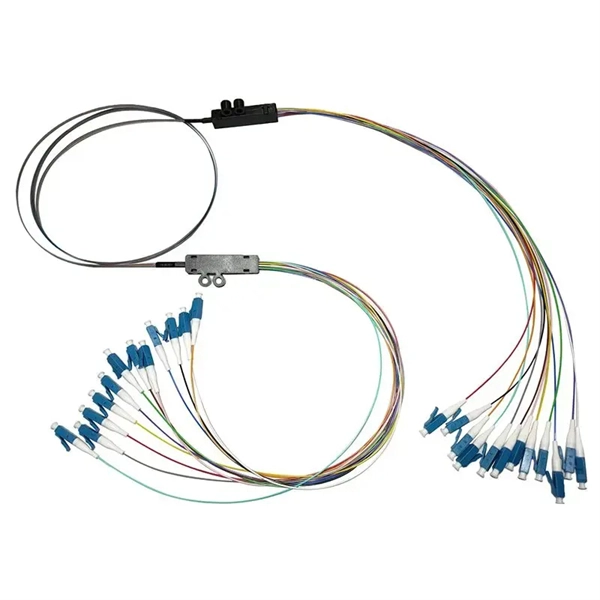
Does a fiber optic splitter need an optical module
The optical transceiver module (like an SFP, SFP+, or XFP module) in the OLT is the laser source that generates the initial light signal. This high-power signal is transmitted down the single fiber. When it reaches the optical splitter, the signal is divided and. These unassuming devices enable a single optical signal to be divided into multiple paths, making them indispensable for sharing network resources efficiently—from residential FTTH (Fiber-to-the-Home) connections to large-scale telecom backbones. This guide demystifies fiber optic splitters. Fiber optic splitter is a passive optical device that includes multiple input and output ends. T PON standards such as GPON, XGS-PON and new 25 and 50G standards. A fiber broadband provider typically determines and overall split ratio for the network, such as 1x32 or 1x64, and uses combinations of splitters to meet that ratio with each PON port. 1x32 splits were common in North America for G-PON architectures. Conversely, it can also combine multiple signals into one.
[PDF Version]
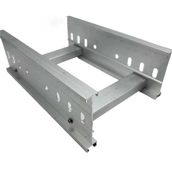
Telecom Racks & Cabinets
19-inch racks, wall-mount cabinets, open frames with high load capacity and seismic rating.
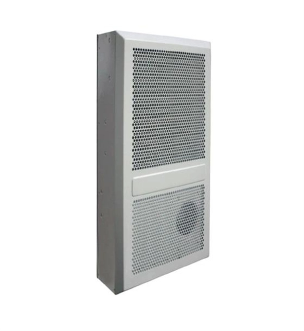
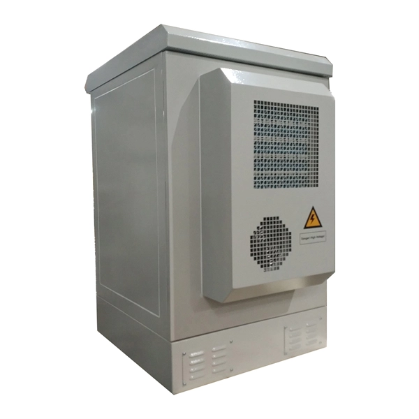
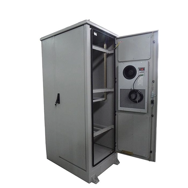
Outdoor Climate Cabinets
IP55/IP66 outdoor enclosures with integrated cooling/heating, -40°C to +55°C operation.
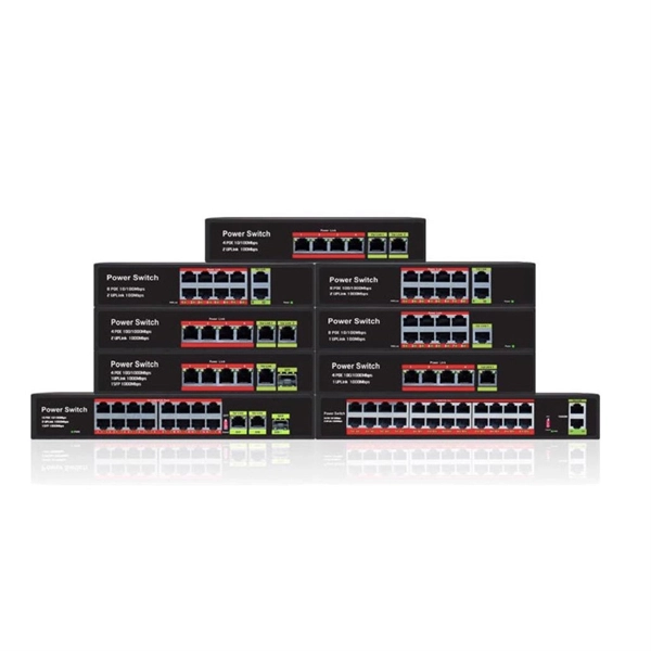
Smart PDUs & Power Distribution
Intelligent PDUs with remote monitoring, per-outlet switching, and environmental sensors.
Shelters & Network Cabinets
Prefabricated telecom shelters, emergency comms shelters, and network cabinets with cable management.