-
How about doing relay protection in a power plant
A protective relay operates by continuously monitoring electrical parameters, detecting abnormalities, making decisions, and triggering circuit breakers to isolate faulty sections. This process helps protect equipment, maintain power system stability, and ensure safety for. A protective relay is an intelligent device that senses abnormal electrical conditions, such as overcurrent, under-voltage, or frequency deviations. They are intended to quickly identify a fault and isolate it so the balance of the system continue to run under normal conditions. It covers the protection methods for generators, transformers, buses, and transmission lines using various relay types to detect and isolate faults efficiently.
[PDF Version]
-
A Brief Analysis of Power Relay Protection
A protective relay operates by continuously monitoring electrical parameters, detecting abnormalities, making decisions, and triggering circuit breakers to isolate faulty sections. This process helps protect equipment, maintain power system stability, and ensure safety for. A protective relay is an intelligent electrical device designed to detect faults in power systems and initiate corrective actions such as tripping a circuit breaker. In modern power systems, nowadays. The rectangular devices are test connection blocks, used for testing and isolation of instrument transformer circuits. 25 years in the electrical industry including 10 years as a MEP consulting engineer. In other words, the prime function of protective relays is the timely and.
[PDF Version]
-
Case Study of Power Supply and Distribution Relay Protection
To improve the reliability of its distribution system, an investor-owned utility in the Southeastern U. New relay panels would be required. Abstract—This paper documents a collaborative effort between the authors' companies to design three separate centralized protection and control (CPC) systems for an existing distribution substation. The first uses a powerful but traditional approach with a microprocessor relay, the second a. Relay protection plays a crucial role in ensuring the safe and reliable operation of electrical power network transmission and distribution systems. Chemical Company in Lote MIDC - Maharashtra Report Prepared by. 101, Gera's Regent Manor, Survey No. 39/570, Behind Opulent Car Care Center Baner, Pune 411045 Tel: 020. This report covers how the addition of distributed resources will impact the distribution relay protection of the system. The issues covered include protective device coordination problems due to infeed and bi-directional current flow; effects on synchronizing and autoreclosing; the potential for.
[PDF Version]
-
Photovoltaic combiner box energy-saving type for relay protection
By centralising connections and integrating protective components, a solar combiner box reduces balance-of-system (BOS) costs, simplifies installation, and significantly enhances the safety and reliability of the entire PV array. Modern solar power stations—from residential rooftops to 1500V industrial arrays—depend heavily on high-quality electrical enclosures, advanced protection components, and intelligent data systems to maintain long-term reliability. They enable centralized management in large-scale and remote installation ity), equipment aging, and poor installation practices. As solar projects grow, so does the wiring complexity. By bringing together multiple circuits, the combiner box also becomes a natural point for overcurrent protection.
[PDF Version]
-
Relay protection CT value
The “C” Class rating of a protection CT is usually shown next to the CT ratio on drawings and performance charts, and is a value in volts. For example, a CT labeled “600:5 C100” has a ratio N = 30 (600/5) and a “C” rating of 100 volts. Keywords: CT MODEL, CT SATURATION, DIFFERENTIAL SLOPE, BLACK START, CT RATIO. Modern relays often have algorithms that enhance the security of elements that are otherwise susceptible to current transformer (CT) saturation. Current transformers for protection relays, as opposed to those use strictly for metering purposes, have an IEEE standard classification. There are two. Combines protection, sensors, control power, and circuit breaker in a single package Typically added to a breaker close circuit to prevent accidental reclosure after a trip. Three fundamental components required for each circuit breaker. Engineers searching this keyword expect practical guidance: formulas, standards references, and integration advice for medium- and low-voltage systems. We explain the differences between symmetrical and asymmetrical sat ration and how remanence accumulates in the core of a CT.
[PDF Version]
-

PW4661 Relay Protection Test
PW466i protective relay test set is an economic model with 6 current channels and 6 voltage channels, capable of automatic testing different kinds of protection relays, such as distance, overcurrent, frequency, directional, time inversed, line‐differential, differential. PW466i protective relay test set is an economic model with 6 current channels and 6 voltage channels, capable of automatic testing different kinds of protection relays, such as distance, overcurrent, frequency, directional, time inversed, line‐differential, differential. PW466i (6×20A, 6×150V) 6-phase relay tester is a powerful secondary injection protective relay testing kit with 6-currents and 6-voltages sources. Functions to give a desired amount of time delay before or after any point of operation in a switching sequence or protective relay system. Serves in conjunction with the device that. Megger offers test sets to cover all these applications, including the SMRT46, which you can configure to supply four voltages and three currents or, alternatively, six currents.
[PDF Version]
-
Relay protection three-stage overcurrent
This protection relay configuration consists of three distinct stages: Instantaneous Overcurrent Protection (Stage I), Time-Limited Overcurrent Protection (Stage II), and Definite-Time Overcurrent Protection (Stage III). So, what distinguishes these stages? How should we understand them? This article explains the three-stage overcurrent protection mechanism, aiming to help electrical. phase overcurrent relays in addition to one residual-ground voltage breaker trip circuits and ground switches. Alternative contact seal-in methods Fig. Elementary diagram of overcurrent relays used with to comply with the requirements for re-energizing feeders. Five-, ten-, and. of ABB's Relion® protection and control product family and its 605 series. This should not be mixed with 'overload' relay protection, which.
[PDF Version]
-
Online Verification of Relay Protection Setting Values
Calculate pickup values, timing curves, coordination time intervals (CTI), and test injection currents for overcurrent (50/51), differential (87), distance (21), and directional (67) protective relays. Essential tool for relay technicians, protection engineers, and. Relay protection is a crucial aspect of electrical power network transmission and distribution systems. According to the method, the regional power grid is divided into multiple subareas according to the practical situation of operation of the regional power grid; a power grid. The North American Electric Reliability Corporation (NERC), under the direction of the Federal Energy Regulatory Commission (FERC), is responsible for improving the reliability of the North American bulk electric system (BES). This responsibility includes creating a compliance program to improve.
[PDF Version]
-
Relay protection near backup protection
Two forms of overcurrent protection are provided: primary protection for the line itself and backup protection for an adjacent line. The paper will briefly discuss the types of HV. Protective Relays - Technical Seminar Nov 2016 - Copyright: IEEE 2 Abstract: Protective relays and devices have been developed over 100 years ago to provide “lastline”of defense for the electrical systems. This discussion includes how modern microprocessor-based relays can benefit the power system whe properly applied to pilot protection and backup step-distance schemes. Reasons for Main Relay Failure: Main.
[PDF Version]
-

Relay Protection Additional Section
This document supplements PJM Manual 07 which contains the minimum design standards and requirements for the protection systems associated with the bulk power facilities within PJM. Power System Protective Relays: Principles & Practices Protective Relays - Technical Seminar Nov 2016 - Copyright: IEEE 1 Power System Protective Relays: Principles & Practices Presenter: Rasheek Rifaat, P. Eng, IEEE Life Fellow IEEE/IAS/I&CPSD Protection & Coordination WG Chair Jacobs Canada. PRC-005-6 Protection System, Automatic Reclosing, and Sudden Pressure Relaying Maintenance and Testing October 2015 ii PRC‐005‐6 Supplementary Reference and FAQ – October 2015 Table of Contents Table of. Product Specialist (West Region) for Digital Substation Products at ABB Inc. Currently residing in Denver, Colorado. Previous experience in designing low voltage and medium voltage switchgear, relay panels and custom control panels as an Electrical Engineer at ESSMetron, Denver CO. The applicable protective standards of this section apply to all Generators interconnecting to PG&E's Transmission Power System at 50 kV or above.
[PDF Version]
-
Where is the relay protection trip contact located
Inside most remote-tripping circuit breakers is an auxiliary contact (sometimes designated “52a”) connected in series with the trip coil. The protection relay tripping circuit refers to the critical electrical control loop that executes trip/close commands from protective relays to circuit breakers, ensuring rapid fault isolation in power systems. This system integrates protection logic with breaker control functions. As we will see in this chapter, there is a wide. Usually located on the cubicle door or at a remote control panel, the control switch is employed for the manual operation of a circuit breaker through electrical control. Master trip relay is not a monitoring relay. It. Master trip relay or lockout relay, also known by ANSI code 86, holds a significant position as an intermediator between the protection relay and control points, even though it is not self-equipped with fault sensing capabilities. Proficient in all ABB/GE medium and low voltage distribution products.
[PDF Version]
-

What instruments are used for relay protection
These devices safeguard assets and maintain power stability by swiftly detecting and isolating faults. This guide explores the different types of protection relays and their testing procedures, with a focus on tools like secondary injection test sets and three-phase relay test sets. The relays are in round glass cases. : 4 The first. Sophisticated test hardware and software solutions to analyse the entire protection system performance. A. Protection systems in power networks are essential for the safe and dependable operation of electrical equipment that includes Transmission lines. 8 kg and offers 4x300V and 6x20A outputs. Its maximum current can reach 60A, and the output power reaches 200VA/Phase.
[PDF Version]
-
Characteristics of zero-sequence component in relay protection
Zero sequence components, also known as residual components, describe the common-mode behavior of the system: All three components have the same magnitude and phase (0° phase shift). Symmetrical components in power systems (positive, negative, and zero sequences) are indispensable tools for power system engineers dealing with unbalanced conditions in three-phase systems. This method, first introduced by Charles Fortescue, simplifies complex scenarios, enabling easier fault. A zero-sequence voltage relay is a protective device designed to detect imbalances in three-phase power systems by measuring the zero-sequence voltage component. This component arises when the vector sum of the three-phase voltages (Va, Vb, Vc) is non-zero, indicating an asymmetrical fault or. fault type identification, fault direction identification, and fault discrim nation in general. Not influenced by load, they contribute to protection speed and sensitivity. Covers CT configurations, sensitivity analysis, application guidelines, and compliance with IEC 61869 and IEEE C57.
[PDF Version]
-
Voltage transformer ratio for relay protection
The relay uses a standard equation to set TAPn, based on settings entered for the particular winding (n denotes the winding number. ): The ratio TAPmax / TAPmin ≤ 7. 5Protection Settings Calculations for Power Transformers i. SEL-787 Transformer Differential Protection The relay (SEL-787) use the transformer MVA rating as a common reference point, TAP scaling converts all sec-ondary currents entering the relay from the two windings to per unit values, thus. In this technical article, we will delve into the comprehensive methodology of calculating the differential relay settings for the GE P642 relay. Like Differential, IDMT, overcurrent, REF, Earth fault E/F, Over flux, Over/Under voltage protection relay setting. Setting procedures are only discussed in a general nature in the material to follow. A Current Transformer (CT) safely scales the primary current to a standardized secondary (commonly 5 A or 1 A) while providing galvanic isolation. Correct CT selection and application directly influence: Billing accuracy: Misapplied ratio or accuracy class can cause revenue leakage or disputes.
[PDF Version]
-
Improving the Quality and Efficiency of Relay Protection Professionals
Better understanding the performance of relays is very important in maintaining the reliability and security of power system. Function testing involves manual or electrical manipulation of components to confirm signal paths and device operation. This paper explores new solutions for performance analysis of transmission line protective relays. These practices mitigate common errors. This handbook covers the code of practice in protection circuitry including standard lead and device numbers, mode of connections at terminal strips, colour codes in multicore cables, dos and donts in execution. Developing and applying intelligent relay protection systems has become an important way.
[PDF Version]
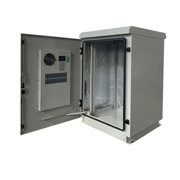
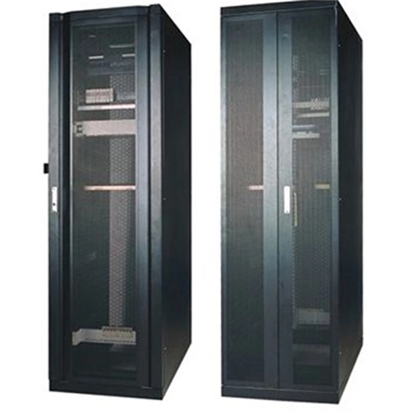
Telecom Racks & Cabinets
19-inch racks, wall-mount cabinets, open frames with high load capacity and seismic rating.
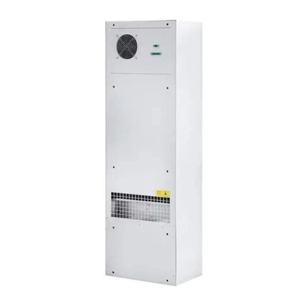
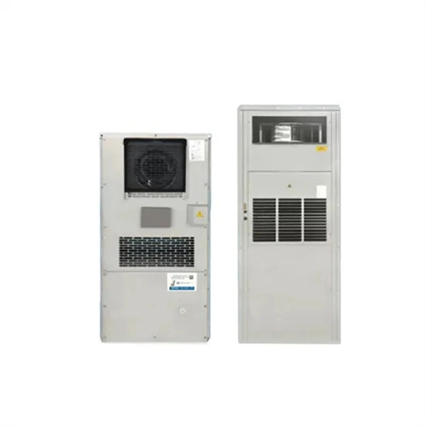
Outdoor Climate Cabinets
IP55/IP66 outdoor enclosures with integrated cooling/heating, -40°C to +55°C operation.
Smart PDUs & Power Distribution
Intelligent PDUs with remote monitoring, per-outlet switching, and environmental sensors.
Shelters & Network Cabinets
Prefabricated telecom shelters, emergency comms shelters, and network cabinets with cable management.