-

Testing of Optical Digital Relay Protection
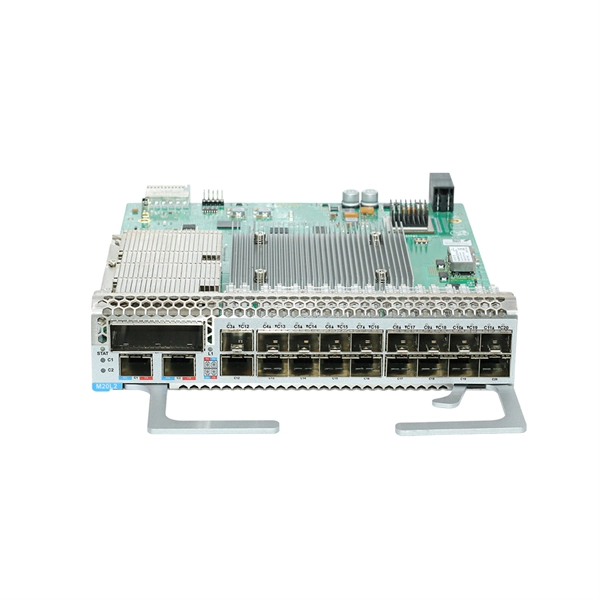
Our relay protection tester offers comprehensive testing for both optical digital and traditional protective devices. It's ideal for power plants, substations, equipment manufacturers, and institutions needing relay protection evaluations. They are like the “eyes” and “nerves” of the system, constantly monitoring the health status of the power grid and quickly responding to faults to ensure the safety of personnel and equipment. To ensure the. This product integrates an optical digital network signal analyzer and an optical digital relay protection tester. Comprehensive and practical testing functions, supporting AC tests, group tests, status sequences, phase verification, polarity, virtual terminals, differential protection, distance. IEC Standard 61850 Optical Digital Relay Protection Test System GDJB-61850 Product Description developed this new portable product.
[PDF Version]
-
Selection of OTDR Testing Module for Smart Cities
This guide covers 8 top models ranging from budget-friendly options under $300 to enterprise-grade professional units. Our team evaluated these units based on dynamic range capabilities, dead zone performance, wavelength support, build quality, and real-world user feedback. To help navigate the wide range of OTDR test solutions available, this OTDR selection and OTDR price quote tool will help guide you to the right OTDR Test solution for your needs. Start by simply selecting your application from the five categories below and answer the questions to proceed to your. Finding the best OTDR fiber optic testing equipment can mean the difference between a quick network fix and hours of troubleshooting in the field. This guide explains: ■ What Is OTDR Testing and Why Does It Matter? An OTDR sends laser pulses into the fiber and measures returning backscatter to create. 1992 New option for testing fiber right in the field (FCS-100 (FCS-100 singlemode singlemode OTDR OTDR card) card) We We introduced introduced a a lighter, lighter, more more compact compact OTDR OTDR than than anything anything else else on on the the market.
[PDF Version]
-
What is the wavelength for testing pigtail fibers
If the span is 64 km (40 miles) or less in optical distance, it will be tested at both wavelengths (1550 and 1310). Both units must have a dynamic range suitable for long-haul applications (spans greater than 120 km) and short distance testing. Why? Because the temperature can. While the center wavelength is listed for each laser diode, this is only a typical number. The aveling down a fiber along different paths. Each path will have a slightly different length which will result in differen arrival times for each component of li ht. This note also provides background information on system link configurations, test equipment and system component considerations that influence.
[PDF Version]
-
Standard for Compression Testing of Optical Cable Sheaths
The IEC 60811 series specifies internationally recognised test methods for non-metallic insulating and sheathing materials used in electric and optical fibre cables. These include thermoplastic and thermosetting compounds such as PVC, PE, PP, and cross-linked materials. We describe how this reliability relates with the various processing steps before the cable is eventually put into service - e. Published by the International Electrotechnical Commission, it defines the mechanical, environmental, and optical tests that every cable must pass before it can be. What are IEC value-added products? Electric and optical fibre cables - Test methods for non-metallic materials - Part 201: General tests - Measurement of insulation thickness IEC 60811-201:2012+AMD1:2017+AMD2:2023 gives the methods for measuring the insulation thicknesses which apply to the most. ards bodies (ISO member bodies). Sections are included for project management; cable handling, testing and equipment; overhead cable placement; underground cable placement; underground enclosures; bonding and grounding; cable.
[PDF Version]
-
Latest Standards for Air Inflation Testing of Optical Cables
3‑E “Optical Fiber Cabling and Components Standard” was developed by the TIA TR‑42. Corning Optical Communications manufactures quality flame retardant optical fiber cables for indoor applications, which comply with the requirements of the National Electric Code® (NEC® 2023) published by the National Fire Protection Agency (NFPA). Please make sure. IEC 60794 is the international standard series governing the design, construction, and performance verification of fibre optic cables. Published by the International Electrotechnical Commission, it defines the mechanical, environmental, and optical tests that every cable must pass before it can be. Recommendation ITU-T L. Note that Recommendation ITU-T L. In order to verify whether the cabling system meets the relevant requirements, it is necessary to conduct relevant tests.
[PDF Version]
-
Find Chip and Packaging Testing of Optical Modules
Most significantly, leading providers of AI and HPC devices like NVIDIA and Intel are pursuing a variety of probing methods, fiber alignment strategies, and connector approaches to determine the best methods for testing at the wafer, package, and system levels. By moving optical transceivers from the fronts of racks into the same package as the networking switch and HBMs, AI programs that used to. This paper discusses the evolution of both conventional and advanced packaging technologies and outlines future directions for design, fabrication, and packaging using glass substrates and femtosecond laser processing. Introduction The challenges in modern HPC, AI, and data communication systems. Information and communication technology (ICT) is projected to drive 20% of global electricity consumption by 2030, with data centers at the heart of the demand. It's critical. At the same time, to achieve larger capacity and higher integration, development of optical interfaces using Co-Packaged Optics (CPO) technology, which are fundamentally different form to current optical transceiver interfaces, is in progress. The CPO is a package in which an optical module and a.
[PDF Version]
-
What are the methods for testing the reliability of pigtail fibers
There are several common methods used to assess various aspects of fiber optic performance, including continuity testing, insertion loss testing, return loss testing, and Optical Time Domain Reflectometer (OTDR) testing. Testing the integrity and performance of fiber optic cables is essential for maintaining the reliability and efficiency of telecommunications networks. Key tests include: Effective fiber testing utilizes advanced tools such as Optical. The primary purpose of fiber integrity testing — required by Telcordia GR-468-CORE, Issue 2 for all optoelectronics and integrated modules with fiber pigtails — is to ensure the attachment of a fiber pigtail to a package. The three main methods for fiber optic.
[PDF Version]
-
Optical Power Meter Linearity Testing
Calibrating the loss scale is a matter of checking the linearity of the power measurement against a calibrated optical power meter, e. We explain the measurement standards, systems, methods, and uncertainties related to. This technical note discusses the optical power linearity test procedure used by ILX Lightwave, and presents the results of high power linearity testing on the ILX Lightwave OMH-6780B Power/WaveHead used with the OMM-6810B Optical Multimeter. This makes regular calibration of test and measurement equipment one of the most. Many factors must be considered when performing absolute power calibration and linearity tests of power meters: the uncertainty calculations, the test methods, the necessary equipment, and the industry standards. If we find a performance problem with the received instrument, we will let you know. You can also ask for a linearity.
[PDF Version]
-
Relay Protection Commissioning Specialist
1,148 Relay Protection Commissioning jobs available on Indeed. Apply to Commissioning Engineer, Commissioning Manager, Designer and more!Job Summary: Seeking a highly skilled and experienced Commissioning Manager to oversee the commissioning and startup activities of energy storage projects. This role will ensure that all projects are commissioned in accordance with company standards, regulatory requirements, and industry best. The testing and verification of relay protection devices can be divided into four groups: Type tests are needed to prove that a protection relay meets the claimed specification and follows all relevant standards. Since the basic function of a protection relay is to correctly function under abnormal. Senior Relay Settings Engineer - Salt Lake City, UT. Electrical commissioning is the process of validating that newly installed or modified equipment performs to OEM specifications and integrates seamlessly with protection and control schemes. This is distinct from maintenance testing, which verifies performance over time. Electrical panels (up to 480V 3-phase).
[PDF Version]
-
Causes of overload in air compressor relay protection
The motor overload relay is designed to protect the motor from damage due to overcurrent. When it trips repeatedly, the motor is either drawing too much current (mechanical or electrical problem), or the relay itself has degraded and become oversensitive. However, on most air compressors with a single phase motor attached in which I came across never seemed to be included or wired with a separate overload protection device but only had a OCPD short circuit ground fault circuit breaker installed upstream to the motor. What is the Thermal Overload on an Air Compressor? The thermal overload, also known as the overload relay or thermal block, safeguards the compressor from damage by. This article explains the main causes of current overload, including unstable voltage, high discharge pressure, air-end problems, and clogged oil separators. Capacitors in VFD drives can hold dangerous voltage.
[PDF Version]
-
Types of Relay Protection Tripping
A protection relay tripping circuit connects relays to breakers for fast fault isolation. Key components include trip/close coils and anti-pumping relays. Proper design, testing, and maintenance ensure reliable overcurrent, differential, and auto-reclosing protection in power. Tripping relays are used to multiply the number of contacts available, provide isolation between the source and system operating element and meet the required duty. In some applications, the relay contacts may have to be rated to carry heavy and highly inductive currents and this requires large. Protective Relay Definition: A protective relay is an automatic device that senses abnormal conditions in electrical circuits and triggers actions to isolate faults.
[PDF Version]
-
Online Verification of Relay Protection Setting Values
Calculate pickup values, timing curves, coordination time intervals (CTI), and test injection currents for overcurrent (50/51), differential (87), distance (21), and directional (67) protective relays. Essential tool for relay technicians, protection engineers, and. Relay protection is a crucial aspect of electrical power network transmission and distribution systems. According to the method, the regional power grid is divided into multiple subareas according to the practical situation of operation of the regional power grid; a power grid. The North American Electric Reliability Corporation (NERC), under the direction of the Federal Energy Regulatory Commission (FERC), is responsible for improving the reliability of the North American bulk electric system (BES). This responsibility includes creating a compliance program to improve.
[PDF Version]
-
Voltage transformer ratio for relay protection
The relay uses a standard equation to set TAPn, based on settings entered for the particular winding (n denotes the winding number. ): The ratio TAPmax / TAPmin ≤ 7. 5Protection Settings Calculations for Power Transformers i. SEL-787 Transformer Differential Protection The relay (SEL-787) use the transformer MVA rating as a common reference point, TAP scaling converts all sec-ondary currents entering the relay from the two windings to per unit values, thus. In this technical article, we will delve into the comprehensive methodology of calculating the differential relay settings for the GE P642 relay. Like Differential, IDMT, overcurrent, REF, Earth fault E/F, Over flux, Over/Under voltage protection relay setting. Setting procedures are only discussed in a general nature in the material to follow. A Current Transformer (CT) safely scales the primary current to a standardized secondary (commonly 5 A or 1 A) while providing galvanic isolation. Correct CT selection and application directly influence: Billing accuracy: Misapplied ratio or accuracy class can cause revenue leakage or disputes.
[PDF Version]
-
Matching ratio of relay protection transformers
This guide focuses primarily on application of protective relays for the protection of power transformers, with an emphasis on the most prevalent protection schemes and transformers. Principles are empha.
[PDF Version]
-
Relay protection aviation plug
Rated to MIL-DTL-5015 specifications, these connectors are compatible with other products that meet the same standard. They can withstand high-vibration applications and frequent connection and disconnection. Ideal for professional and personal projects. Relay Socket is a versatile component identified by BACS16W2A. This socket features a threaded stud mounting method, allowing for secure installation in various configurations. With a maximum overall length of 1. Explore our full line of molded components for aviation, including parts designed to meet common MIL/NAS. Please note, Aircraft Spruce ®'s personnel are not certified aircraft mechanics and can only provide general support and ideas, which should not be relied upon or implemented in lieu of consulting an A&P or other qualified technician. Aircraft Spruce ® assumes no responsibility or liability for any. Designed and manufactured by Aircraftplugs. 3 PINS NATO AN2551 standard plug, made of strong polycarbonate, registered plug.
[PDF Version]
Telecom Racks & Cabinets
19-inch racks, wall-mount cabinets, open frames with high load capacity and seismic rating.
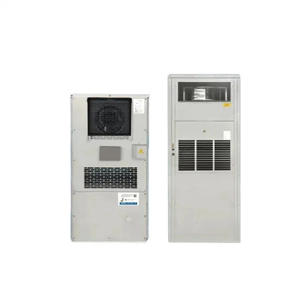
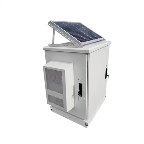
Outdoor Climate Cabinets
IP55/IP66 outdoor enclosures with integrated cooling/heating, -40°C to +55°C operation.
Smart PDUs & Power Distribution
Intelligent PDUs with remote monitoring, per-outlet switching, and environmental sensors.
Shelters & Network Cabinets
Prefabricated telecom shelters, emergency comms shelters, and network cabinets with cable management.