-
Calculation of Fiber Optic Patch Cord Splice Points
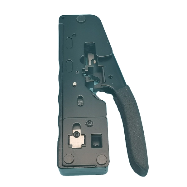
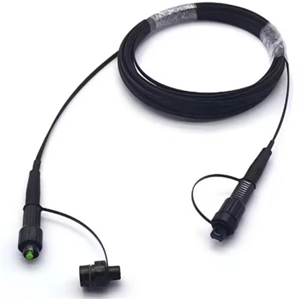
This calculator keeps optics, glass travel, and active forwarding separate so you can see where distance and delay enter the link. A fiber optic pigtail is a short length of optical fiber cable with a factory-terminated connector on one end and a bare, exposed fiber on the other. Unlike a patch cord—which has connectors on both ends—the bare fiber end of a pigtail is designed to be permanently spliced (either by fusion or. Estimate one-way and round-trip timing for fiber runs, optics, and active hops in home labs and backbone links. Direct point-to-point links with OS2 single-mode 1310 nm typically use 10 km+ of practical reach. 2 * Rear cable entries accommodate cables with diameter below 10mm. Splice loss depends on workmanship, fiber type, and method. Enter values based on recent OTDR traces, contractor QA records, or manufacturer. bers to be terminated from cable to cable or from cable to pigtail assemblies.
[PDF Version]
-
What to do if the fiber optic cable splice loss is too high
If high loss persists, inspect the splicer's alignment system. Clean the V-grooves and objective lenses with appropriate cleaning sticks and isopropyl alcohol. Dirt or dust on the fibre ends is one of the most common causes of high splice loss. Fusion splicers have settings that must be tailored to your fibre type and condition. Modern fiber optic networks usually keep splice loss low, as shown below: You should know that each splice can add 0. Understanding its causes and solutions is critical for reliable fiber optic installations. Poor Fiber Cleave: Angled or chipped cleaves prevent proper. Neglecting minor problems can lead to higher splice losses, increased signal attenuation, and long-term damage to fibre networks. This. One problem I continue to see is unexpected high loss during spicing between exchange-to-exchange network, particularly in the feeder and backbone segments, which can seriously impact the performance of the PON networks.
[PDF Version]
-
How to calculate fiber optic splice attenuation
The calculator essentially performs the following calculation: Total Attenuation (dB) = (Attenuation Coefficient * Cable Length) + (Number of Connectors * Connector Loss) + (Number of Splices * Splice Loss)The calculator essentially performs the following calculation: Total Attenuation (dB) = (Attenuation Coefficient * Cable Length) + (Number of Connectors * Connector Loss) + (Number of Splices * Splice Loss)This calculator helps you estimate the total attenuation (signal loss) in a fiber optic cable link. Here are the details and instructions about each field and how they contribute to the calculation: 1. Attenuation Coefficient (dB/km): This value represents the inherent signal loss per kilometer of. Model optical links with practical engineering inputs fast. Review attenuation, splice, connector, and splitter effects. Check total loss, power margin, and feasibility clearly.
[PDF Version]
-
Fiber Optic Cold Splice Installation
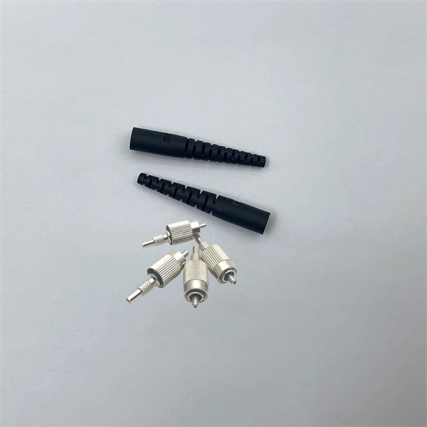
This step-by-step fiber optic cold splicing tutorial makes it easy for beginners and professionals. They protect and organize the sensitive connection points between optical fibres and play a decisive role in the quality, reliability and ease of maintenance of the entire network. While connectors. Optical fiber Lengjie is used for optical fiber butt optical fiber or optical fiber docking pigtail, which is equivalent to making a joint, (fiber docking pigtail refers to the butt joint between the optical fiber and the core of the pigtail, not the pigtail head mentioned by the former), used for. Fiber optics is the fastest and one of the safest ways to transmit information online.
[PDF Version]
-
How long should the fiber optic cable splice box be
The proper length of fiber is needed to allow splicing and then neatly storing fiber in the splice tray. Inside splice closures and at each end, cables with metallic shielding or strength members must be properly grounded and bonded. Clean the loose tube and the reinforced core sheath with a cleaning agent, remove the excess filling tube, and polish the cable sheath 150mm long with the. Installing a fiber optic splice closure efficiently and effectively requires attention to detail and adherence to specific procedures. Here's a structured guide to ensure optimal installation, protecting the integrity of your fiber optic network connections. They protect the cable splices from physical damage, moisture, and other environmental factors.
[PDF Version]
-
Function of Fiber Optic Cold Splice Terminal Connector
Fiber optic cold connection, also known as mechanical splicing, is a widely used method of connecting optical fibers in a network. Unlike fusion splicing, which uses heat to join two optical fibers together, cold connection uses mechanical means to create a stable and low-loss. Should you use connectors or splices? In this lesson, a long and very important one, you will learn about fiber splicing and termination. Fiber optic joints or terminations are made two ways: 1) splices which create a permanent joint between the two fibers or 2) connectors that mate two fibers to. Fiber optic joints or terminations are made two ways: 1) splices which create a permanent joint between the two fibers or 2) connectors that mate two fibers to create a temporary joint and/or connect the fiber to a piece of network gear. In this. Executive Summary: A fiber optic pigtail is one of the most commonly specified yet least understood components in structured cabling.
[PDF Version]
-
Fiber Optic Splice Box Inspection Report
This template supports fiber optic splicing work by guiding teams through key documentation and quality checks. Record the job details (conducted on, prepared by, location) and the joint name, then capture photographic evidence of strength members, internal splicing across all trays and splitters. All Rights Reserved. fCONSTRUCTION QUALITY REQUIREMENTS FOR FTTP & SSP Work Orders This document provides Construction Technicians, Construction Managers, FTTP/SSP Vendors, and Inspectors with the essential information to ensure a quality build and to successfully pass an Outside Plant Inspection. Inspect the splice enclosure for any damage or defects. Verify that all components are accounted for. 5 dB and prevent costly network outages caused by contaminated connectors. They define a minimum baseline of quality and workmanshi for installing electrical products and systems.
[PDF Version]
-
Color of two cores in drop fiber optic cable splice
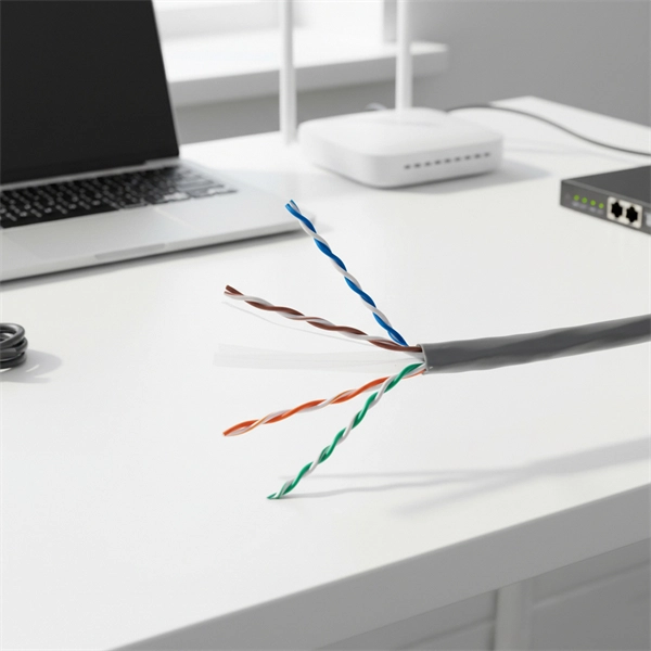
The outer jacket color is the fastest way to identify the cable's core functionality. Critical Exception: Outdoor cables are almost always black (for UV resistance), regardless of the fiber inside. Understanding fiber‑optic color codes is essential for any technician tasked with installing, maintaining, or troubleshooting modern fiber networks. By adopting the TIA/EIA‑598C standard, you gain a universal “language” of colors that speeds identification, reduces miswiring, and enhances safety. Color codes are used in fiber optics to identify fibers, cables and connectors.
[PDF Version]
-

6-core fiber optic cold splice from a supplier in the 10 ASEAN countries
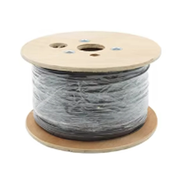
Explore reliable optical fiber splice closures for network deployment. Our closures prioritize reliability, installability, and flexibilitySingle-core fiber optic cables have a core diameter of 8 to 10 microns and one thin glass strand. They use only one core to transmit data, providing an exceedingly clear signal over long distances. Because of their low signal attenuation, they are ideal for long-distance telecommunications and data. Used for fiber butt splicing fiber or fiber splicing pigtail, this is equivalent to making a splice, and the thing used for this kind of cold splicing is called an optical fiber cold splice. They also offer FBA freight services. Durable ABS material, 3-year warranty. FIS' New CA6+ Core Alignment Fusion splicer is the latest addition to the FIS Fusion Splicing product line. With the Contractor always in mind, the CA6+ is faster, more durable, and easier to use than ever. Fully compatible with FIS Cheetah and Armordillo Splice-On Connectors, this is the perfect.
[PDF Version]
-
How to tie fiber optic cables to a fiber optic splice tray
Secure tight bufered cables using cable ties threaded through holes in the tray (Figure 5). IMPORTANT: Multiple pigtails may be secured with a single cable tie. Fiber cable splicing is the process of permanently joining two optical fibers end-to-end to allow light signals to pass through with minimal loss. Unlike fiber connectors, which can be plugged and unplugged, splicing creates a fixed connection that is typically more stable and has lower insertion. By following these detailed steps, the installation of your Fiber Splice Closure will be secure, organized, and maintained, ensuring high performance and longevity of your fiber optic network. Whether you're installing a new network, expanding an existing one, or. In this guide, we cover the basics of fiber optic splicing, how to perform splicing using two different methods, and finally some best practices to perform good fiber splicing. Ensure Your Splicing Tools are Clean – #2.
[PDF Version]
-
How to connect the four fiber optic splice boxes
Learn how to splice fiber optic cable using fusion splicing with this complete step-by-step guide. Includes tools, best practices, loss standards (ITU-T G. 652), cost analysis, and FAQs for network engineers and installers. Fiber cable splicing is the process of permanently joining two optical fibers end-to-end to allow light signals to pass through with minimal loss. Unlike fiber connectors, which can be plugged and unplugged, splicing creates a fixed connection that is typically more stable and has lower insertion. This guide explores everything about fiber optic cable splice —from fiber fusion splice basics to how to splice fiber cable step-by-step—covering tools, techniques, and practical tips. Ensure Your Splicing Tools are Clean – #2. Use and Maintain Your. This article will guide you through the necessary tools, materials, and methods on how to connect fiber optic cables effectively, ensuring you achieve optimal performance from your fiber optic network. Have a network installation project? Fiber Optic Cables: The primary medium for your connections. The unit will accommodate four 12-inch splice organizer trays (Corning p/n:.
[PDF Version]
-
Fiber optic cold splice temperature resistance
The closure works in -35° C to 70°C environments, is cold and heat resistant, ofers electrical insulation, and is resistant to chemical corrosion. Note: Any fiber count upto 96F can be accomodated in this closure. The fiber optic dome splice closure is well-suited for splicing, distributing variable optical cables, and splitting. The solid box shell and the main structure are built to withstand harsh environments. The dome closure also protects fiber optic cables from vibration, impact, stretching, twisting. Optical fiber's ability to withstand extreme heat and cold directly impacts signal integrity, network reliability, and maintenance costs, especially in harsh environments like industrial facilities, outdoor installations, and data centers. This comprehensive guide answers the question: “How much. Abstract—This study explores the efficacy of thermal splicing conditions between silica and zirconium-fluoride fibers, focusing on achieving mechanical strength between the two fibers. Moreover, this is for 48 single fusion splices. These devices use mechanical closures.
[PDF Version]
-

How long is the optical fiber in the fiber optic splice tray
This fiber splice is 11-¾ inches long, 4-⅛ inches wide, and 7/16 inches height. You can splice up to 24 fibers spliced in this tray. Some Velcros are included to. Corning splice trays use proven designs and fiber organization technology to provide optimum physical protection for fusion and mechanical splicing methods. The trays are engineered for use with indoor or outdoor splice hardware with both loose tube and tight-buffered optical cable designs. Its role in containing such splices includes the protection of splices from environmental and mechanical strain determinants that would otherwise affect the effectiveness of the. Introducing the Speedway splice tray with unrivaled ease of use and flexibility.
[PDF Version]
-
What quota should be used for fiber optic splice closures
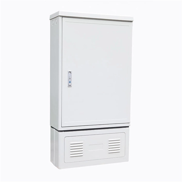
Selecting the right splice closure for each FTTx node—whether a dome-type model with a capacity of up to 144 fibers for feeder networks or a compact in-line fiber closure with up to 96 fibers for distribution—ensures optimal performance, simplified maintenance, and long-term. Selecting the right splice closure for each FTTx node—whether a dome-type model with a capacity of up to 144 fibers for feeder networks or a compact in-line fiber closure with up to 96 fibers for distribution—ensures optimal performance, simplified maintenance, and long-term. The selection of the appropriate fiber optic splice closure can be a very daunting task. There are many possible ways to put two or more cables together or drop a single fiber at a location. Patch panels often have splice closures built-in, especially when the patch panel has many connections. Special splice trays are in the back of the rack or on sliding trays. They are engineered systems designed to protect fiber splices from mechanical stress, environmental exposure, and long-term performance degradation.
[PDF Version]
-
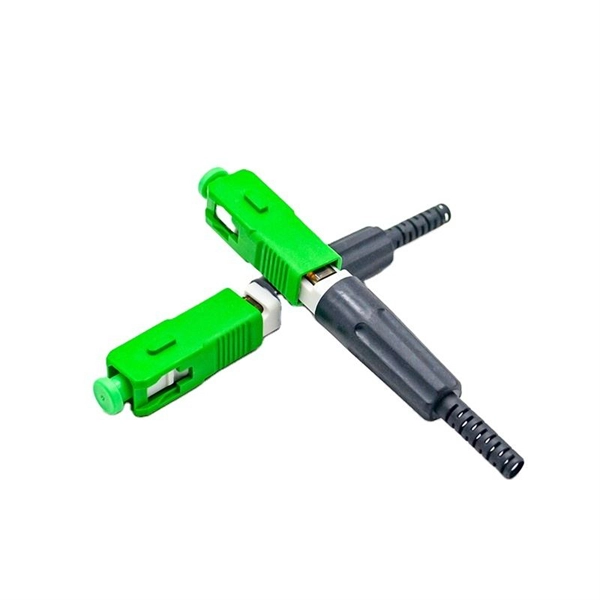
How to connect two fiber optic cables with a cold splice
In this step-by-step tutorial, learn how to splice fiber optic cables like a pro — perfect for telecom technicians, network engineers, and field techs. For network managers and technicians, a poor splice can lead to significant signal degradation, network downtime, and costly troubleshooting. At Turn-Key. Optical fiber fast connectors, also known as cold connectors, are becoming increasingly popular due to their ease of use and quick installation. Unlike traditional fiber connectors that require epoxy and polishing, fast connectors use a mechanical splice to join the fibers. This article explains when. Fiber optic splicing is the art and science of joining two separate optical fibers to create a continuous light path. Ensure Your Splicing Tools are Clean – #2.
[PDF Version]
Telecom Racks & Cabinets
19-inch racks, wall-mount cabinets, open frames with high load capacity and seismic rating.
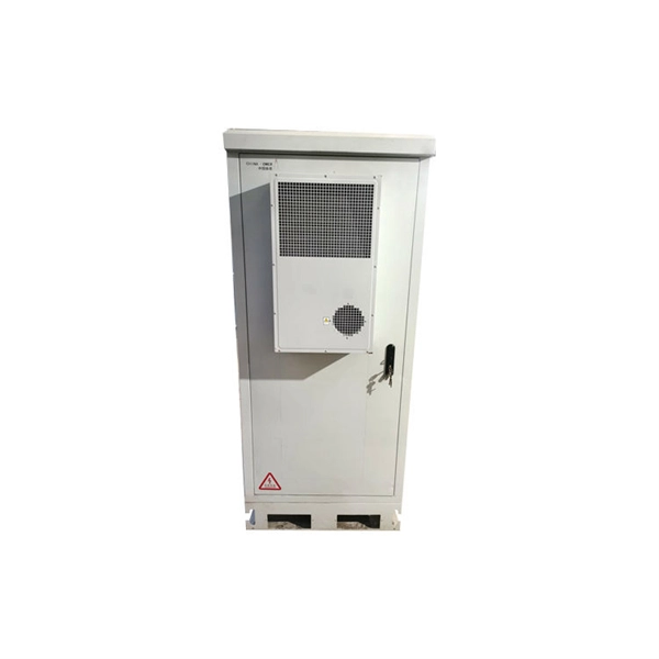
Outdoor Climate Cabinets
IP55/IP66 outdoor enclosures with integrated cooling/heating, -40°C to +55°C operation.
Smart PDUs & Power Distribution
Intelligent PDUs with remote monitoring, per-outlet switching, and environmental sensors.
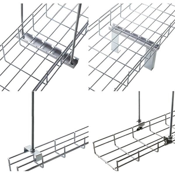
Shelters & Network Cabinets
Prefabricated telecom shelters, emergency comms shelters, and network cabinets with cable management.