-
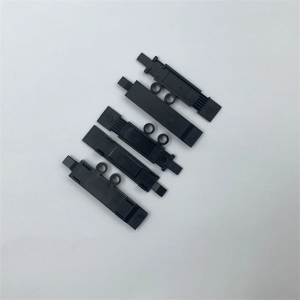
Is flexible optical fiber the same as a pigtail
When you build or upgrade a fiber network, the same four words pop up everywhere— fiber optic (bare fiber), pigtail, patch cord, optical cable. They're related, but they are not interchangeable. Mixing them up drives costs higher, increases loss, and slows your rollout. The good news? Once you nail. Executive Summary: A fiber optic pigtail is one of the most commonly specified yet least understood components in structured cabling. Get the wrong connector type, the wrong polish, or skip proper fusion splicing technique—and you're looking at elevated signal loss, increased back reflection, and a. Dual Connectors: Both ends are fitted with standardized connectors (e., LC, SC, ST), which may be identical (e. It is usually suitable for field termination using a mechanical or fusion splicer. But what exactly is a pigtail and why do you use it? In this article, we explain why they are important and which pigtail connector you should choose, with a focus on SC and LC pigtails. What is a pigtail? A pigtail is used to.
[PDF Version]
-
Comparison of the hazards of electrical cables and optical fibers
These factors introduce electrical hazards that technicians must be aware of to stay safe. Unlike older copper-based systems, fiber optic cables rely on light rather than electrical current to move data, fundamentally altering the nature of any potential hazard. Understanding the differences between these technologies is the first step in accurately assessing the real-world risks, which. When most people think of safety in fiber optic installations, the first thing that comes to mind is eye damage from laser light in the fiber. They have an image of a laser burning holes in metal or perhaps burning off warts. Optical fibers are commonly used for data transmission in industrial environments, particularly when cable runs exceed 100 meters and copper Ethernet is no longer viable.
[PDF Version]
-
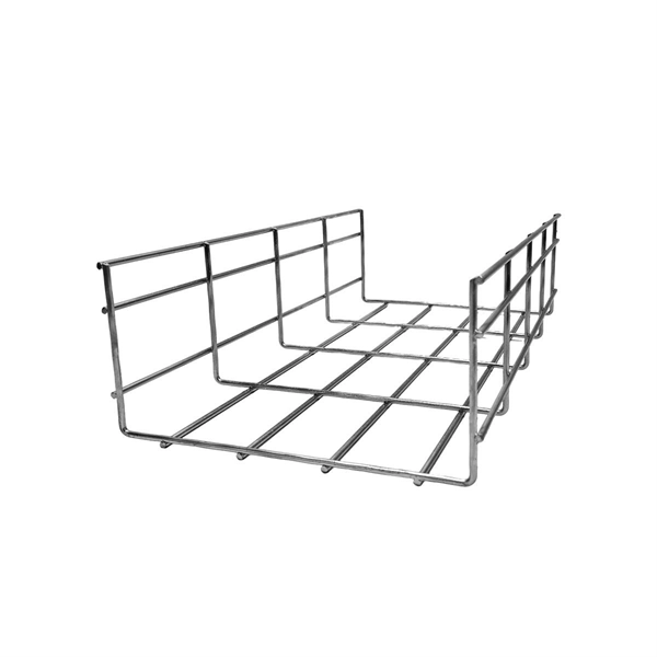
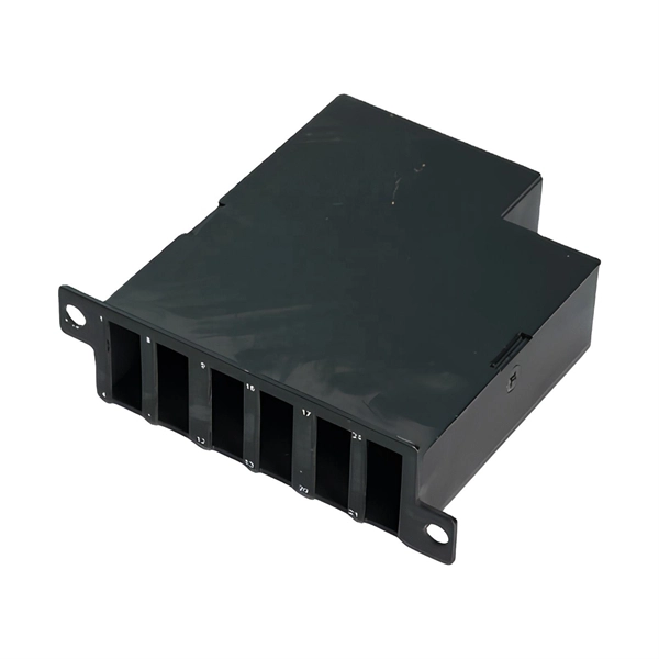
How to quickly thread optical fibers into cable trays
Quickly learn how to properly splice an optical fiber into a standard splicing tray. Laser light can be invisible and can damage your eyes. Viewing it. Fiber cable splicing is a critical step in building reliable fiber optic networks. Whether in data centers, telecom rooms, or outdoor FTTx deployments, proper splicing inside a fiber enclosure ensures low signal loss, long-term stability, and easy maintenance. Since prices of optical fiber and its associated electronics are becoming more competitive to copper, and availability is increasing, many. WARNING: Never look directly into the end of a fiber that may be carrying laser light. Viewing it directly does not cause pain. The iris of the eye will not close involuntarily as when viewing a bright light. Consequently, serious damage to the. In this guide, we cover the basics of fiber optic splicing, how to perform splicing using two different methods, and finally some best practices to perform good fiber splicing.
[PDF Version]
-
Electromagnetic waves communicate via optical fibers
Fiber optic communication relies on transmitting information as pulses of light through thin strands of glass or plastic called optical fibers. Instead of using electrical signals (like in traditional copper wires), it uses electromagnetic radiation in the form of light. This technology has revolutionized data transmission, enabling high-speed, long-distance communication for. Light is part of the "electromagnetic spectrum" that also includes x-rays, ultraviolet radiation, microwaves, radio, TV, cell phones, and all the other wireless signals. We refer to the range of wavelengths of electromagnetic. When light travels through an optical fiber, only reflections at a certain angle are reflected repeatedly due to the relationship between the difference in refractive index (between the core and cladding of the optical fiber) and the thickness of the core.
[PDF Version]
-
Can outdoor black optical fibers be made into multimode
All three formats can be built with either single mode or multimode fiber (single mode being far more common for several reasons — learn more) and in a variety of strand counts. These cables are specifically designed to ensure reliable connections in outdoor applications. Multi-mode links can be used for data rates up to 800 Gbit/s. Multi-mode fiber has a fairly large core diameter that enables multiple light modes to be. Single-mode (SMF) and multi-mode fiber (MMF) use different core sizes, sources and wavelengths. These differences determine which transceivers work with which fiber and how far signals can travel. Understanding the compatibility constraints prevents costly downtime and troubleshooting. Single-mode. Product Description This is a black 1000 foot spool of indoor/outdoor rated fiber optic distribution cable intended for large installations of short range runs at LAN Speeds. 5 microns, compared to the ~9-micron core in single-mode fiber.
[PDF Version]
-
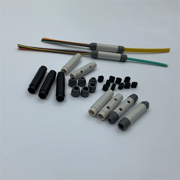
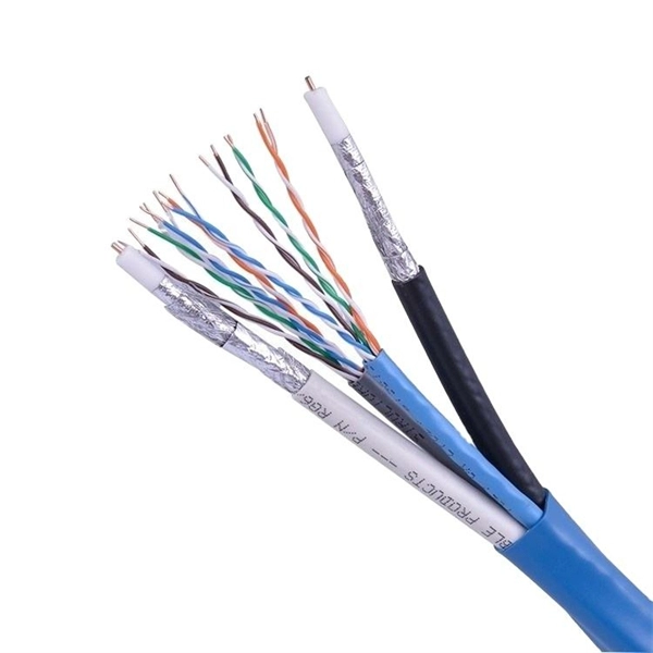
Optical cables are tightly bundled optical fibers
For some applications, some number of optical fibers is bundled together, forming a fiber bundle or fiber-optic bundle. In most cases, one uses multimode large-core silica fibers or plastic fibers.
[PDF Version]
-
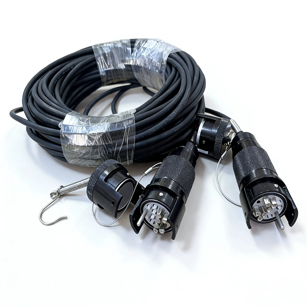
Can optical fibers and optical cables be interconnected
Using fiber cross connect provides scalability, reliability, flexibility, high-speed data transfer, and cost-efficiency in a telecommunications network. Fiber cross connect refers to a network junction where optical fibers from different sources are interconnected to form a single, larger network. This article will explain the benefits and challenges of fiber cross connect. It will also provide a simple guide to the types, uses, key components. In integrated circuits, optical interconnects refers to any system of transmitting signals from one part of an integrated circuit to another using light. Optical interconnects are used to connect different parts of a fiber optic system and are a key. Optical interconnects are systems that connect devices such as computers and data centers to each other at high speeds using light. This allows efficient transmission of data and power between server to server, rack to rack, module to module, backplane to backplane, board to board, and chip to chip.
[PDF Version]
-
High Temperature Resistance Selection Guide for Surveillance-Grade Coherent Optical Modules
Different from the previous selection guide based on optical module parameters, this article focuses on actual scenarios to help you choose the right optical module in high temperature application environment and optimize cost and maintenance strategies. Use our AOCs to accelerate storage, data, and computing connectivity, while reducing weight and power compared to traditional copper. >Signal blur: The laser wavelength is. So when choosing a transceiver that would be best suited for your needs, it is best to check which temperature range would be best. There are two types of temperature ranges – operating temperatures and storage temperatures. This article delves into the significance of industrial-grade optical modules. For engineers in telescope manufacturing and satellite payload design, the challenge is twofold: achieving dimensional stability using thermally stable substrates against extreme thermal cycling, and maintaining clarity via radiation-hardened coatings under sustained radiation exposure.
[PDF Version]
-
Complete Color Matching Chart for Optical Cables
This guide explains the latest EIA/TIA-598-D fiber color-coding standard used to identify fiber types, inner fiber sequences, and connector polish styles. With clear tables and updated details, it serves as a comprehensive reference for technicians handling modern fiber optic. The standard fiber color code chart includes Blue, Orange, Green, Brown, Slate, White, Red, Black, Yellow, Violet, Rose, and Aqua for 12 primary fibers. Purpose of Color Coding in Fiber Optics: Fiber optic color coding is primarily used to organize and identify individual fibers within a cable. By adopting the TIA/EIA‑598C standard, you gain a universal “language” of colors that speeds identification, reduces miswiring, and enhances safety across cable jackets, connectors, buffer tubes, and splice trays. It helps with fiber optic splicing color code procedures, repairs, and network setups. The blue unit has the first 12 fibers and.
[PDF Version]
-
Selection Guide for LPO Optical Modules and SFP for Smart Buildings
This article focuses on four cores: market trends, scenario-based selection, compatibility tips, and Finisar adaptation, providing practical selection solutions for enterprises, carriers, and data centers. An LPO (Linear Pluggable Optics) solution offers considerable power savings for optical interconnect by removing the digital signal processing (DSP) function from the pluggable optical module. This architecture takes advantage of the capabilities in each segment of the link to form a power, cost. SFP (Small Form-factor Pluggable) is a compact, hot-pluggable network interface module used to connect network devices (switches, routers, firewalls) to fiber optic or copper cables. In modern Ethernet networks, choosing the wrong transceiver can result in link failures, speed mismatches, compatibility errors, or unexpected distance limitations. For network engineers, system integrators, and IT. SFP Optical Module Selection Guide: A Comprehensive Overview for 2025 Selecting the right SFP optical module can be daunting. 800G has become the mainstream.
[PDF Version]
-

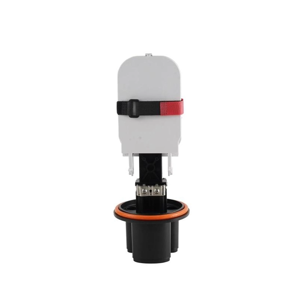
ONT Optical Network Terminal EML Selection Guide for Oil Pipeline Monitoring
This Operational Telecom Network for the Connected Pipeline System Design Guide documents best practice design of safe, highly available, and secure infrastructure and applications for Oil and Gas pipelines. SLB's pipeline integrity monitoring systems—part of the Optiq™ fiber-optic solutions family—enable pipeline operators to perform accurate leak detection and pig tracking while protecting pipelines from third-party intrusions and detecting ground movements, such as earthquakes and subsidence. Using. FEBUS Optics offers a complete solution for oil and gas pipeline monitoring to: detect any risks caused by natural events. Pipeline operators and LNG terminal operators face unique and demanding challenges. ONTs are mandatory for fiber – routers cannot replace them. These cables collect and analyze vibration signals to accurately paint a picture of any construction events threatening pipeline.
[PDF Version]
-
Selection Guide for 10G Optical Network Terminals at Distribution Network Automation Level
Answering this urgent call, FS offers a comprehensive portfolio of XG (S)-PON ONUs designed to meet diverse deployment scenarios. This guide will help you select the right hardware to unlock the full potential of your PON network. Understand what an ONT really does, how it differs from a router or modem, and how to select the right ONT class for FTTH, enterprise and campus fiber projects – with clear decision rules for engineers and procurement. For scenarios requiring symmetric bandwidth and ultra-low latency. Our SDX 6000 Series of software-defined optical line terminals (OLTs) consists of open and disaggregated access devices that support a broad range of PON standards, including 10G Combo PON, XGS-PON, GPON, and 10G-EPON. These devices are built using modern design principles. The Tellabs FlexSym Optical. The GigaPoint® GP1100G is an indoor, 2. 5 Gbps GPON ONU small form-factor service delivery terminal providing one 2. 5 Gigabit Ethernet (GE) interface delivering IPTV video and data services, and one voice line supporting carrier-grade VoIP (SIP).
[PDF Version]
-
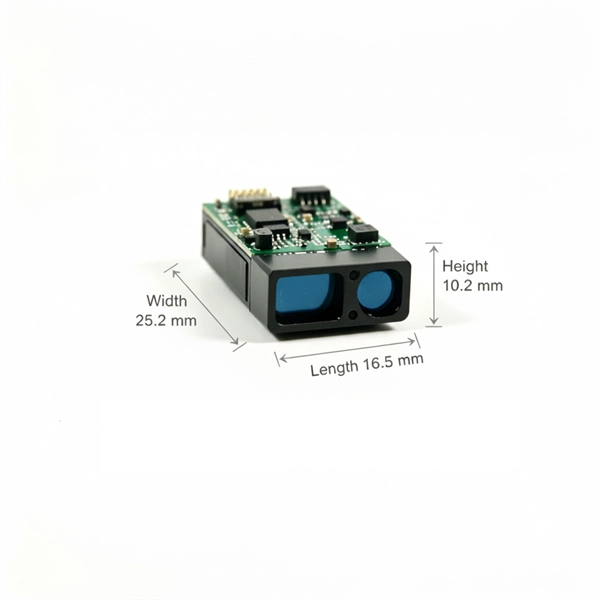
Selection Guide for Low-Noise Active Optical Modules for Metropolitan Area Networks
Faced with a variety of models such as SR4/LR4/ER4, how should engineers choose? This article uses 5 major classification dimensions + practical selection solutions to help you overcome the selection difficulties! 1. Packaging Determines Performance Boundaries: 100G QSFP28 VS CFPWhether it's a fiber optic module or a complete optical line card, Texas Instruments' highly integrated, low power, “across the board” solutions enable leading designs for 10 Gigabit Ethernet, SONET, Fibre Channel, or any proprietary application. For transceivers and other high-speed interfaces, TI. An optical module usually consists of an optical transmitting device (TOSA, including a laser), an optical receiving device (ROSA, including a photodetector), functional circuits,main control circuit board (PCBA), housing and optical (electrical) interface and other components. How do optical. Optical modules are pivotal components in optical fiber communication systems, operating at the physical layer—the foundational level of the OSI model. Their primary role is to facilitate optoelectronic conversion, transforming electrical signals into optical signals, and vice versa.
[PDF Version]
-
Selection Guide for Low-Temperature Resistant Long-Distance Optical Transceivers for Broadcast Transmission
This guide helps network engineers and field techs select telecom-grade optics for long-distance transmission, validate compatibility, and troubleshoot failures using measurable checks. What does “long haul fiber optic” mean in practice? Should I trust the datasheet. A long distance transceiver is an optical module designed to transmit Ethernet or data center traffic over extended single-mode fiber (SMF) links, typically ranging from 10 km to 120 km without intermediate regeneration. Radiall designs rugged active optical transceivers specifically to meet these challenges. So incase your network ever leaves the. ) and ultra-long working distance (ULWD) options. These compact, hot-swappable devices support high-speed data links across campuses, metro networks, data center.
[PDF Version]
-
High-Precision Selection Guide for Safe City-Level Optical Receivers
We have a reputation for building high quality, robust receivers that incorporate innovative patented technology to help you keep on working in the toughest job site conditions. Which receiver is right for you? Need something else?Fiber-Optic Receivers: Amplified high-speed fiber-optic receivers offer bandwidths up to 38 GHz for receiving fiber-optic data while delivering the lowest noise and cleanest responses possible. Defined as a device that detects and translates invisible or barely visible laser beams into readable signals, a laser. An optical receiver is an electronic device that detects and converts optical signals into electrical signals. The. When selecting the best optical receiver for your fiber optic communication system, prioritize compatibility with your existing network infrastructure, required bandwidth, and transmission distance.
[PDF Version]
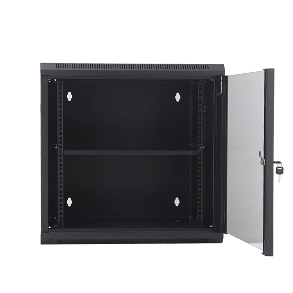
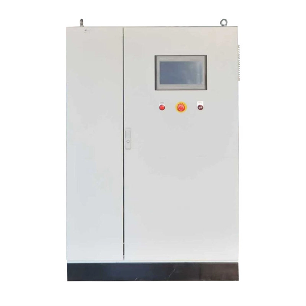
Telecom Racks & Cabinets
19-inch racks, wall-mount cabinets, open frames with high load capacity and seismic rating.
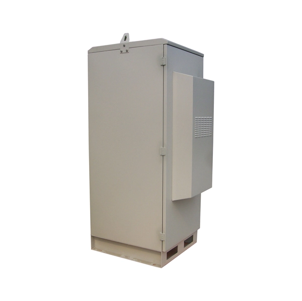
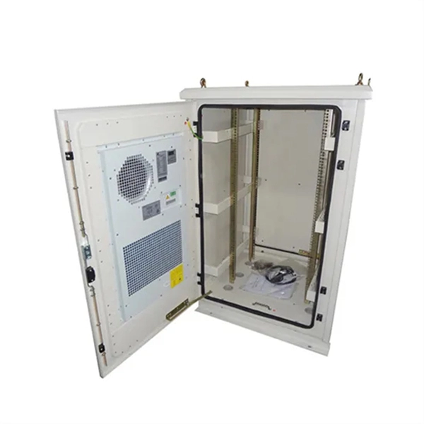
Outdoor Climate Cabinets
IP55/IP66 outdoor enclosures with integrated cooling/heating, -40°C to +55°C operation.
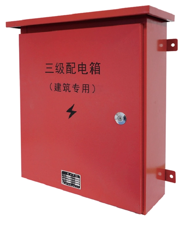
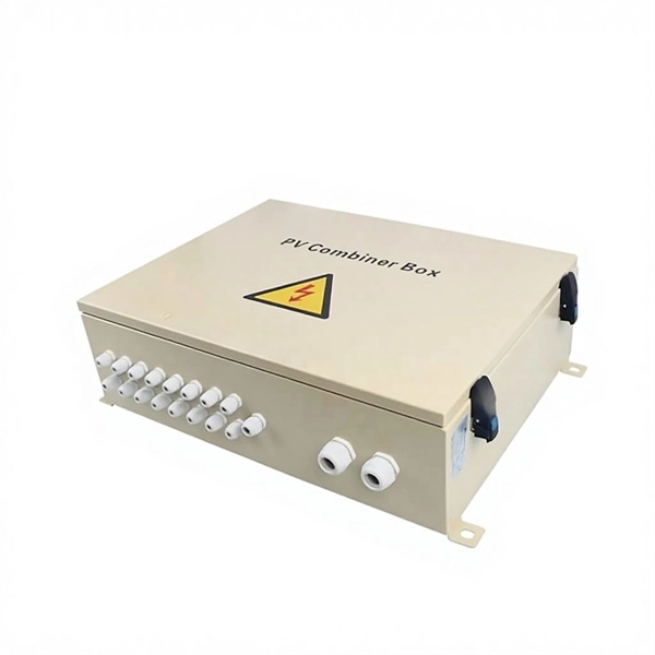
Smart PDUs & Power Distribution
Intelligent PDUs with remote monitoring, per-outlet switching, and environmental sensors.
Shelters & Network Cabinets
Prefabricated telecom shelters, emergency comms shelters, and network cabinets with cable management.