-

Wired transmission media include optical fiber
Wired media: The physical connection between two communication devices that carries the signal from one side to the other. Common wired media include twisted pair, coaxial cable, and optical fiber. Wired communication offers reliability and stability, but requires cabling and can be inconvenient for mobile devices. With guided media, the waves are guided along a solid medium. Wireless transmission media, as the name suggests, refers to the technology used to transmit information from one device to another without the use of a physical connection.
[PDF Version]
-
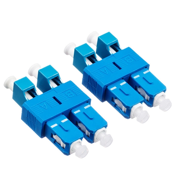
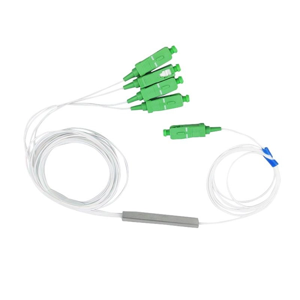
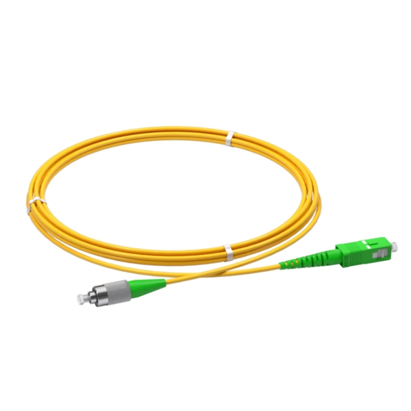
How to tell the front from the back of a fiber optic patch cord
The ferrule end face of the patch cord is ground into different structures. PC, APC, and UPC are three different ferrule polishing methods, representing the structural differences of the front face of the ceramic ferrule. As shown below, the ferrule is the housing for the bare end of an optical. At ZION Communication, we design and manufacture a full range of fiber patch cords for: This guide will help you quickly understand the main types of fiber patch cords and how to choose the right solution for your project – and how ZION can support you with stable quality, flexible customization. Here at Fiber Optic Center, we believe it's important to introduce engineers and technicians to various aspects of the production process to manufacture high-performance, world-class fiber optic cable assemblies. Ideally, your finished fiber optic cable assembly will meet all relevant international. Fiber optic patch cords, also known as fiber optic patch cables or fiber jumpers, are indispensable components in modern optical networks. Fiber optic patch cables are found almost everywhere; cable television networks (CATV), data centers, computer networks, and telephone networks.
[PDF Version]
-
How to make a cold joint for double-wire optical fiber
In this video, we will learn how to joint two Fiber Optic Cables together or Fiber Optic Cable splicing #fiber #fibercable #fiberlaser #fibersplicing #fiberc. Fiber optic joints or terminations are made two ways: 1) splices which create a permanent joint between the two fibers or 2) connectors that mate two fibers to create a temporary joint and/or connect the fiber to a piece of network gear. Either joining method must have three primary characteristics. It is used to connect optical fiber or optical fiber butt pigtail, which is equivalent to making a joint (fiber butt pigtail refers to the butt joint of the fiber core of the optical fiber and the pigtail instead of the pigtail head mentioned in the former), and is used for this kind of cold. At the heart of any robust fiber optic network lies a crucial process: Preparing a fiber cable for termination of a connector or splice. Two types of splices are used in fiber optic cabling one is Mechanical the other is Fusion. What is Fiber Optic Splicing and Why is it Needed? – #1.
[PDF Version]
-

How to connect a single-mode dual-core optical fiber
This guide will break down the professional methods to achieve seamless single-mode to multi-mode conversion, ensuring your network integrity and performance. 📝 Why Can't You Directly Connect SMF and MMF? At its heart, the incompatibility is physical. A fiber media converter takes an Ethernet signal on copper (RJ-45) and converts it to an optical signal on fiber, or vice versa. Single mode light travels in the Ø9 µm core of the fiber, while multimode light propagates in the Ø105 µm inner "1 st cladding". How do we choose, and what are their differences and advantages? Let's learn about this! What is a Single-Fiber (BiDi) Transceiver? Single fiber module also called BiDi transceiver or WDM module.
[PDF Version]
-
Crystalline Silicon for Optical Fiber Communication
Silicon-core fibres have unlocked new regimes of mid-infrared transmission, on-fibre Raman amplification and nonlinear wavelength conversion, finding relevance in gas sensing, biomedical diagnostics, high-power laser delivery and all-optical signal processing. Silicon-core optical fibres represent a convergence of semiconductor photonics and conventional fibre technology, embedding a crystalline silicon or silicon–germanium alloy core within a glass cladding. This architecture combines the high refractive index contrast and pronounced nonlinear response. Polycrystalline silicon core optical fibers have been fabricated by modified thermal annealing of amorphous silicon chemically deposited at high pressure. The resulting fibers have small-diameter cores, a geometry advantageous for optical guidance. Moreover, the combination of chemical deposition. Novel core fibers have a wide range of applications in optics, as sources, detectors and nonlinear response media. Optoelectronic, and even electronic device applications are now possible, due to the introduction of methods for drawing fibres with a semiconductor core. Here we explore the underlying.
[PDF Version]
-
Source manufacturer of optical fiber cables for communication in Democratic Republic of Congo
Genew Technologies and Zhongshi Wosen, both Chinese companies, will help the Democratic Republic of Congo (DRC) build its fiber optic network. Our vision is to become the leading solution provider in Fiber Optic communication system by providing Leading Brands and 'state of the art' services. Its main product is the internet for professionals. Having therefore. The Democratic Republic of Congo (DRC) is poised for a significant boost in its digital infrastructure following the signing of a Memorandum of Understanding (MoU) between the Congolese Optical Fiber Company (SOCOF) and the Agency for Steering, Coordination and Monitoring of Collaboration. SOCOF is a one-person limited company in which the Congolese State is the sole shareholder. It is governed by the Uniform Act revised on January 30, 2014 relating to the law of Commercial Companies and Economic Interest Grouping and by all other laws and regulations in force in the DRC, not.
[PDF Version]
-

The Role of Fiber Core in Optical Cable Splicing
At its core, fiber optic splicing involves joining two pieces of fiber optic cable to ensure that light pulses travel without disruption. This is achieved through fusion splicing or mechanical splices, each offering distinct advantages depending on the project requirements. The goal is to align the microscopic glass cores (typically. In this guide, you will find a chronological description of the fusion splicing process, the principal technical standards, and answers to the real-life questions network engineers and procurement teams may have. Professionals in telecommunications, data centers, and network infrastructure must understand the core functions and why they are fundamental to their fiber optic. The cladding is usually 125 microns in diameter and is uniform across most fiber types. Typically it is stripped away during preparation for fusion splicing. Ensure Your Splicing Tools are Clean – #2.
[PDF Version]
-
Slovakia offers free quotes for multimode optical fiber cables for long-distance connections
TendersOnTime, the best online tenders portal, provides latest Slovakia Optical Fibre tenders, RFP, Bids and eprocurement notices from various states and counties in Slovakia. High-quality fiber cables, connectors, and assemblies for enterprise and infrastructure networks. Fiber connectivity engineered for shock, vibration, temperature extremes, and demanding field. Fiber optic interconnect solutions are ideally suited for high speed, high reliability, EMI/RFI immune, digital data transmission in harsh environment. You can narrow down the list of manufacturers based on their location and capabilities, browse their product catalogs, view their profiles, and send inquiries. Fibre Optic Cables are available at Mouser Electronics.
[PDF Version]
-
What are the different modes of optical fiber fusion splicing
The two primary industry-accepted methods for fiber optic cable splicing are fusion splicing and mechanical splicing. The choice between them depends on performance requirements, budget constraints, and the specific application environment. Fusion splicing is the process of fusing or welding two fibers together usually by an electric arc. This technique ensures high-performance data transmission and is essential in extending cable runs, repairing broken links, or establishing new network paths in data.
[PDF Version]
-

The function of cable and optical fiber cable delivery reel
The core function of a fiber optic cable reel is to facilitate the proper unwinding and spooling of fiber optic cable during installation. This is a delicate process that requires attention to detail. These devices are essential for coiling long, continuous materials such as cables, wires, paper, and. The reels are designed for handling fiber cables in temporary installations. It can be stacked, has room on the inside for storing connectors (size up to Probeam Sr. Whether for temporary setups or permanent installations, our selection of cable.
[PDF Version]
-
How to weld aluminum strips in optical fiber cables
There are several methods to achieve this. The most popular ones include: mechanical welding - with the use of mechanical joints and thermal welding with the use of a welding machine, and the third option, i. the technique of polishing joints and gluing. Optical cable transverse stripping knife, vise, utility knife, scissors, strengthening core cutters, toilet paper and alcohol cotton balls Methods and procedures of optical cable stripping 1, according to the actual determine the cable stripping length, generally in 1. 2, with optical cable. Whether you're a beginner or an experienced welder, this page has all the information you need to successfully weld aluminum using the MIG process. From detailed settings charts that guide you through the intricate world of voltage, amperage, and wire feed speed, to a breakdown of the best aluminum. Fiber Optic Welding How To Joint Fiber Optic Cablesplicing fiber optic cable,fiber optic splice,fiber optic,fiber optics,fiber splice,how to splice,fibre opt. Reheated to. As a premium filler metal solution, Hobart aluminum wire is supported and manufactured by a team with decades of expertise in aluminum filler metals.
[PDF Version]
-
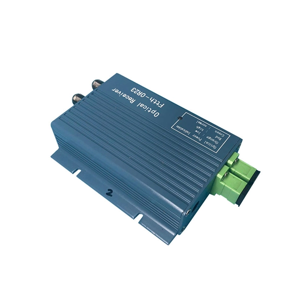
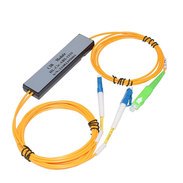
What are the functions of an optical fiber communication control board
Their primary function is to directly boost optical signals without the need for optical-to-electrical conversion, thus preserving signal integrity and extending transmission distances. The diagram above shows how electronic input signals get transformed into light pulses, travel through a fiber optic cable, and are converted back into. Often, optical fiber communication plays a significant role in the development of telecommunication systems with high quality and speed. Nowadays, optical fiber applications majorly involve telecommunication systems with an inclusion of internet and local area networks (LAN) to achieve high. Using fiber optic control circuits provides electrical isolation for safety in hazardous environments. Because optical cables carry no current they are safe to use in explosive environments and eliminate the hazards of short circuits in metal wires and cables.
[PDF Version]
-
Belarusian large-core optical fiber 1310nm
In this article, we explore the key characteristics, common applications, and important comparisons related to 1310nm optical modules. Used for medium-distance links in city networks. As part of the O-band (1260–1360 nm), it balances low dispersion, stable performance, and cost efficiency. This makes it widely adopted in data centers, enterprise backbones, and metro access. The product features an SFP+ package with an LC connector, a 1310nm DFB laser with a PIN photodetector, and supports up to 20km transmission on SMF with power dissipation under 1W. Or It is also suited for analog fiber transmission. Pricing (USD) Filter the results in the table by unit price based on your quantity. A. 10GBASE-LRM SFP+ Transceiver Module 1310nm 220m - FS. com FS United StatesFREE SHIPPING on Orders Over US$79 Contact Us United States / $ USD Sign in Sign up Search Recent Searches Change FREE SHIPPING on Orders Over US$79 United States HomeOptical Transceivers10/25/40/100G. SFP+, 1310nm, LR SMF 10km, 10G DDM, Corning 1LAN-SFPP-10GB-LR Compatible Integra manufactures the highest quality SFPP transceivers in the industry, designed to be 100% interoperable with all OEM platforms.
[PDF Version]
-
Reasons for messy optical fiber cables
Outdoor fiber cables are exposed to temperature changes, moisture, and rodent damage. These factors can weaken the cable jacket and affect performance over time. Though fiber optics is known for reliability, it is not invulnerable. Every fiber optic cable installer or a company that deals in optical installation needs to know the reasons behind. Fiber-optic cables are the backbone of modern connectivity—powering 5G networks, global internet backbones, and data center interconnections with near-light-speed data transmission. Even. A well-built fiber link rarely fails, but when it does the symptoms can be short, confusing, and expensive to chase. This guide lists the actual, field-proven problems technicians encounter most often and gives step-by-step troubleshooting actions you can copy into your maintenance routine. Despite their durability, fiber optic cables can suffer from physical stress. Get to know straight from the fiber optic installers and identify the common causes of fiber optic cable damage to have a solid network infrastructure.
[PDF Version]
-
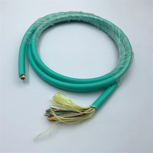
How to separate the fiber cores of OPGW24-core optical cable
Removing the aluminum strands and outer layers of the OPGW cable exposes the fiber optic cores 7, which is essential for proper termination. Use a file to smooth any sharp edges after removing the aluminum strands 8. Carefully separate the metal loose tubes without damaging. Proper termination of OPGW cables involves precise steps like careful handling 3, removing outer layers, cleaning fibers, and securing with clamps. In the construction of electric power dedicated communication network, the number of optical fibers used is usually 12 to 24 cores. With the continuous expansion of system capacity according to new business requirements, the number of cores is gradually increasing, and individual line sections have. out this step, cut a small piece of pipe, about 2 feet, from the free end of the cable and practice cuttin of the cable. While holding the cable, pull the optical units completely out of the pipe by pullin toward the tower. What is Fiber Optic Splicing and Why is it Needed? – #1. First, a heat-shrink tube is placed over the OPGW cable.
[PDF Version]
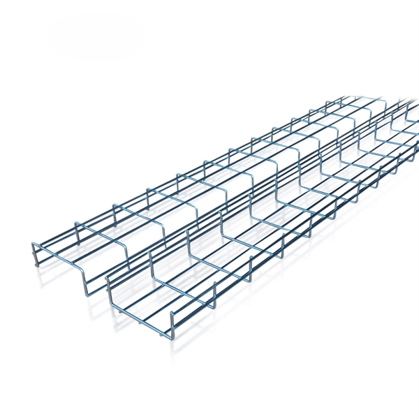
Telecom Racks & Cabinets
19-inch racks, wall-mount cabinets, open frames with high load capacity and seismic rating.
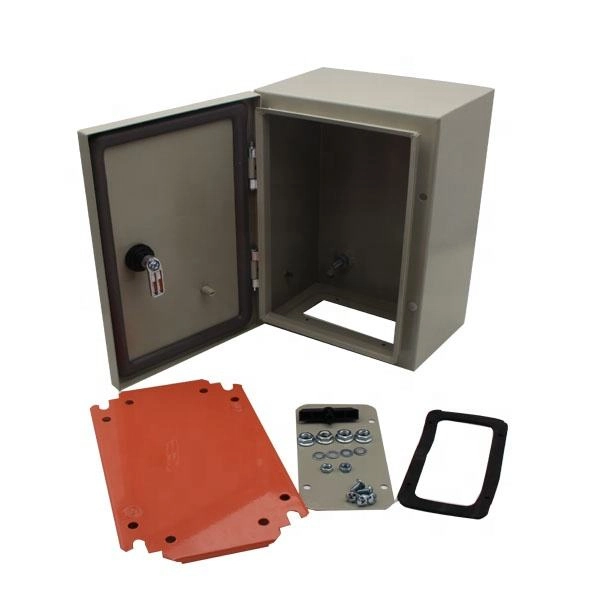
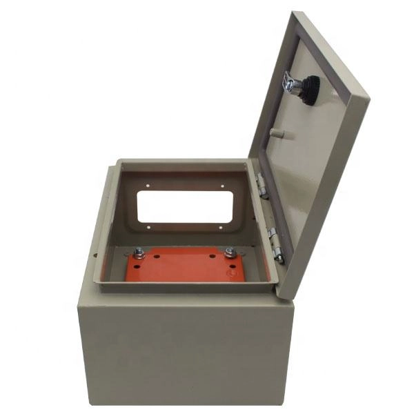
Outdoor Climate Cabinets
IP55/IP66 outdoor enclosures with integrated cooling/heating, -40°C to +55°C operation.
Smart PDUs & Power Distribution
Intelligent PDUs with remote monitoring, per-outlet switching, and environmental sensors.
Shelters & Network Cabinets
Prefabricated telecom shelters, emergency comms shelters, and network cabinets with cable management.