-
Relay Protection Principle of Network Control System
Relay protection is a vital aspect of electrical power systems that ensures the safety and integrity of the network, equipment, and personnel. It is designed to detect and isolate faults or abnormal conditions within the system to prevent damage, minimize downtime, and maintain. The selected protection principle affects the operating speed of the protection, which has a significant im-pact on the harm caused by short circuits. Further, the duration of the voltage. IEEE/IAS/I&CPSD Protection & Coordination WG Chair Jacobs Canada, Calgary, AB rasheek. com IEEE Southern Alberta Section PES/IAS Joint Chapter Technical Seminar - November 2016 Protective Relays - Technical Seminar Nov 2016 - Copyright: IEEE 2 Abstract: Protective relays and devices. The rectangular devices are test connection blocks, used for testing and isolation of instrument transformer circuits. This. This handbook covers the code of practice in protection circuitry including standard lead and device numbers, mode of connections at terminal strips, colour codes in multicore cables, dos and donts in execution.
[PDF Version]
-

Lightning protection grounding wire diameter of distribution box
26 mm 2 (10 AWG) ground wire must be used, and in all other markets a 6 mm 2 must be used. On the US market, a 5. Grounding of the units: Attach a ground wire from one of the threaded studs (A) at the bottom of the housing, to the mounting plate (B). The static. Whether you're a seasoned pro or just starting out, this comprehensive guide will give you practical insights into proper grounding techniques, with a special focus on how selecting quality materials from a reliable building material supplier impacts your entire system's safety and longevity. The National Electrical Code (NEC) provides clear guidelines for ground wire sizing through Table 250. 122, but understanding how to apply these requirements correctly can make the difference between a safe installation and a costly code violation. IN ELECTRICAL STATIONS INCLUDING TRANSMISSION AND DISTRIBUTION SUBSTAT GR THAN 8 FT FROM THE FENCE. THE FENCE SHALL BE GROUNDED SEPARATELY FROM THE GRID UNLESS OTHERWISE NOTED ON THE A PROPRIATE PROJECT DRAWING.
[PDF Version]
-

Relay protection aviation plug
Rated to MIL-DTL-5015 specifications, these connectors are compatible with other products that meet the same standard. They can withstand high-vibration applications and frequent connection and disconnection. Ideal for professional and personal projects. Relay Socket is a versatile component identified by BACS16W2A. This socket features a threaded stud mounting method, allowing for secure installation in various configurations. With a maximum overall length of 1. Explore our full line of molded components for aviation, including parts designed to meet common MIL/NAS. Please note, Aircraft Spruce ®'s personnel are not certified aircraft mechanics and can only provide general support and ideas, which should not be relied upon or implemented in lieu of consulting an A&P or other qualified technician. Aircraft Spruce ® assumes no responsibility or liability for any. Designed and manufactured by Aircraftplugs. 3 PINS NATO AN2551 standard plug, made of strong polycarbonate, registered plug.
[PDF Version]
-
Improving the Quality and Efficiency of Relay Protection Professionals
Better understanding the performance of relays is very important in maintaining the reliability and security of power system. Function testing involves manual or electrical manipulation of components to confirm signal paths and device operation. This paper explores new solutions for performance analysis of transmission line protective relays. These practices mitigate common errors. This handbook covers the code of practice in protection circuitry including standard lead and device numbers, mode of connections at terminal strips, colour codes in multicore cables, dos and donts in execution. Developing and applying intelligent relay protection systems has become an important way.
[PDF Version]
-
Voltage transformer ratio for relay protection
The relay uses a standard equation to set TAPn, based on settings entered for the particular winding (n denotes the winding number. ): The ratio TAPmax / TAPmin ≤ 7. 5Protection Settings Calculations for Power Transformers i. SEL-787 Transformer Differential Protection The relay (SEL-787) use the transformer MVA rating as a common reference point, TAP scaling converts all sec-ondary currents entering the relay from the two windings to per unit values, thus. In this technical article, we will delve into the comprehensive methodology of calculating the differential relay settings for the GE P642 relay. Like Differential, IDMT, overcurrent, REF, Earth fault E/F, Over flux, Over/Under voltage protection relay setting. Setting procedures are only discussed in a general nature in the material to follow. A Current Transformer (CT) safely scales the primary current to a standardized secondary (commonly 5 A or 1 A) while providing galvanic isolation. Correct CT selection and application directly influence: Billing accuracy: Misapplied ratio or accuracy class can cause revenue leakage or disputes.
[PDF Version]
-
Characteristics of zero-sequence component in relay protection
Zero sequence components, also known as residual components, describe the common-mode behavior of the system: All three components have the same magnitude and phase (0° phase shift). Symmetrical components in power systems (positive, negative, and zero sequences) are indispensable tools for power system engineers dealing with unbalanced conditions in three-phase systems. This method, first introduced by Charles Fortescue, simplifies complex scenarios, enabling easier fault. A zero-sequence voltage relay is a protective device designed to detect imbalances in three-phase power systems by measuring the zero-sequence voltage component. This component arises when the vector sum of the three-phase voltages (Va, Vb, Vc) is non-zero, indicating an asymmetrical fault or. fault type identification, fault direction identification, and fault discrim nation in general. Not influenced by load, they contribute to protection speed and sensitivity. Covers CT configurations, sensitivity analysis, application guidelines, and compliance with IEC 61869 and IEEE C57.
[PDF Version]
-
Where is the relay protection trip contact located
Inside most remote-tripping circuit breakers is an auxiliary contact (sometimes designated “52a”) connected in series with the trip coil. The protection relay tripping circuit refers to the critical electrical control loop that executes trip/close commands from protective relays to circuit breakers, ensuring rapid fault isolation in power systems. This system integrates protection logic with breaker control functions. As we will see in this chapter, there is a wide. Usually located on the cubicle door or at a remote control panel, the control switch is employed for the manual operation of a circuit breaker through electrical control. Master trip relay is not a monitoring relay. It. Master trip relay or lockout relay, also known by ANSI code 86, holds a significant position as an intermediator between the protection relay and control points, even though it is not self-equipped with fault sensing capabilities. Proficient in all ABB/GE medium and low voltage distribution products.
[PDF Version]
-
Matching ratio of relay protection transformers
This guide focuses primarily on application of protective relays for the protection of power transformers, with an emphasis on the most prevalent protection schemes and transformers. Principles are empha.
[PDF Version]
-
What are the different types of surge protection for primary distribution boxes
Switches / isolator: Controls circuits and provides shut-off for maintenance. What are the different types of SPDs and their application? 1. Type 2 + 3 SPD Can an SPD also protect against a Temporary Overvoltage? It is important that our electronic devices and connections work all the time. As the preeminent electrical code in the country, the National Electrical Code. Surge protectors (Surge Protective Devices, SPD) installed in distribution board panels are primarily used to protect electrical equipment from transient voltages (surges or spikes) caused by lightning strikes, power grid fluctuations, or other factors. It improves safety by enabling protection against overload and short circuits, and it improves reliability by keeping circuits separated and clearly. The five main benefits of putting a surge protector in your distribution box are: Lightning surges can get into a building's wires during storms. Surge protectors here act like a shield. They stop too much voltage.
[PDF Version]
-
Overall Start-up Principle of Relay Protection
The article provides an overview of protective relaying principles and their applications for high-voltage power system components. It covers the protection methods for generators, transformers, buses, and transmission lines using various relay types to detect and isolate faults efficiently. Graduated with a Master of Science in Electrical Engineering from The University of Texas at Dallas in 2018 and with a Bachelor of. A protective relay is basically an electrical device that detects a fault in a power system and initiates the operation of the circuit breaker to isolate the defective section or component from the rest of the system.
[PDF Version]
-
The five characteristics of relay protection refer to
The five basic facets are: Reliability: assurance that the protection will perform correctly. Selectivity: maximum continuity of service with minimum system disconnection. A protective relay is an electrical switch which can automatically operate when a fault or any other abnormal conditions occur in the electrical system. It sends a signal to turn on the alarm or indicator or trip a circuit breaker to separate the faulty part from the healthy section. The primary. The rectangular devices are test connection blocks, used for testing and isolation of instrument transformer circuits. Its main purpose is to safeguard electrical equipment like transformers, generators, and transmission lines from damage due to. Characteristics of Protective Relay elements using different operating principles.
[PDF Version]
-
Relay Protection Additional Section
This document supplements PJM Manual 07 which contains the minimum design standards and requirements for the protection systems associated with the bulk power facilities within PJM. Power System Protective Relays: Principles & Practices Protective Relays - Technical Seminar Nov 2016 - Copyright: IEEE 1 Power System Protective Relays: Principles & Practices Presenter: Rasheek Rifaat, P. Eng, IEEE Life Fellow IEEE/IAS/I&CPSD Protection & Coordination WG Chair Jacobs Canada. PRC-005-6 Protection System, Automatic Reclosing, and Sudden Pressure Relaying Maintenance and Testing October 2015 ii PRC‐005‐6 Supplementary Reference and FAQ – October 2015 Table of Contents Table of. Product Specialist (West Region) for Digital Substation Products at ABB Inc. Currently residing in Denver, Colorado. Previous experience in designing low voltage and medium voltage switchgear, relay panels and custom control panels as an Electrical Engineer at ESSMetron, Denver CO. The applicable protective standards of this section apply to all Generators interconnecting to PG&E's Transmission Power System at 50 kV or above.
[PDF Version]
-

Electric shock protection for distribution box busbars
Busbar insulator supports block conductive paths between electrical parts. Busbars (bus bars) are integral to power distribution and serve numerous industries including automotive, industrial, and aerospace. I once shared these insights with Pranav, a buyer from the. Literature review has shown that small distribution substations used for medium voltage make use of overcurrent relays to provide busbar protection and large substations make use of differential protection schemes. This technical article explains a busbar theory at the distribution network level. They typically have a horizontal arrangement designed to accept multi-pole and/or single pole OCPDs. If you know. This guide outlines best practices for selecting, installing, and protecting electrical components to maintain safety, efficiency, and compliance with industry standards.
[PDF Version]
-
Where to connect the relay protection device
Where possible, use a close-nippled connection with wires going directly to the first breaker at the top of a panel. It is used in transformer outgoing isolation panel or. Locate the SPD as close as possible to the panel to be protected. CT's transform line current down to a signal level that is. Protective relays are used in industrial power generation and supply systems to open and isolate branch circuits in the case of excessive current. They are activated by means which are not dependent on a continual AC supply. Relays provide these benefits; 1.
[PDF Version]
-
Causes of overload in air compressor relay protection
The motor overload relay is designed to protect the motor from damage due to overcurrent. When it trips repeatedly, the motor is either drawing too much current (mechanical or electrical problem), or the relay itself has degraded and become oversensitive. However, on most air compressors with a single phase motor attached in which I came across never seemed to be included or wired with a separate overload protection device but only had a OCPD short circuit ground fault circuit breaker installed upstream to the motor. What is the Thermal Overload on an Air Compressor? The thermal overload, also known as the overload relay or thermal block, safeguards the compressor from damage by. This article explains the main causes of current overload, including unstable voltage, high discharge pressure, air-end problems, and clogged oil separators. Capacitors in VFD drives can hold dangerous voltage.
[PDF Version]
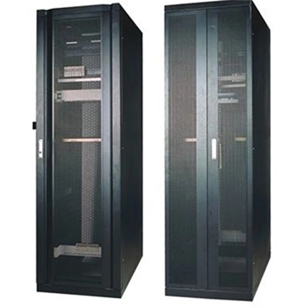
Telecom Racks & Cabinets
19-inch racks, wall-mount cabinets, open frames with high load capacity and seismic rating.
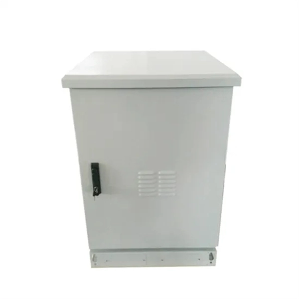
Outdoor Climate Cabinets
IP55/IP66 outdoor enclosures with integrated cooling/heating, -40°C to +55°C operation.
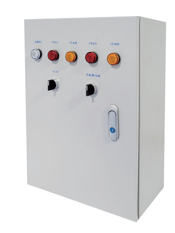
Smart PDUs & Power Distribution
Intelligent PDUs with remote monitoring, per-outlet switching, and environmental sensors.
Shelters & Network Cabinets
Prefabricated telecom shelters, emergency comms shelters, and network cabinets with cable management.