-
How to patch fiber optic cable to a switch
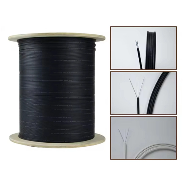
Most modern fiber-enabled network switches require an SFP transceiver module featuring a duplex (two strand) multimode OM3 or duplex single mode OS2 connection with LC connectors. Direct attach cables with pre-terminated SFP connections may also be used. Download the. In today's high-performance networks, fiber optic patch cables are the lifelines that ensure smooth data flow across switches, servers, and routers. Even the most advanced optical transceivers can only perform at their peak when paired with properly installed, clean, and precisely managed fiber. Fiber patch panels are important components that are used to help organize and protect fiber optic cables. Connecting a fiber patch panel to a switch is a critical step in setting up a fiber optic network. Step 2: Identify the splitter number. These individual strands will then connect to electronic devices.
[PDF Version]
-
How to connect fiber optic cables to a Huijue switch
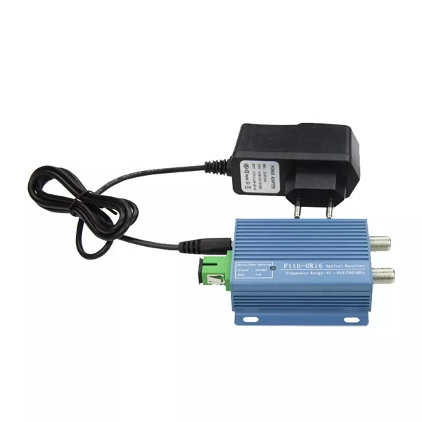
In this video, we'll delve into the world of fiber optics, exploring the reasons behind their necessity, introducing Fiber Switches and Fiber PoE Switches, guiding you through the selection of the right fiber optic cables, and demonstrating the physical. In this video, we'll delve into the world of fiber optics, exploring the reasons behind their necessity, introducing Fiber Switches and Fiber PoE Switches, guiding you through the selection of the right fiber optic cables, and demonstrating the physical. This section describes how to install optical transceivers on the SFP or SFP+ ports and connect them to the ports of the peer device using optical fibers according to the network plan. The USG supports both 1 Gbit/s, 10 Gbit/s, and 40 Gbit/s optical modules. The optical modules at both ends are. Connecting a switch to a fiber optic network involves several steps and requires specific equipment to ensure a successful and efficient connection. Fiber optic technology is widely used in networking due to its high-speed data transmission capabilities and long-distance coverage. Fiber optic switches utilize.
[PDF Version]
-
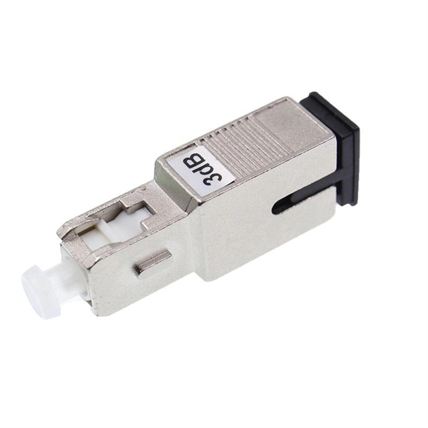
How do I switch the fiber optic cable to red light source mode
Turn on the optical visual fault locator. Most VFLs have a button or switch to turn on the light. You should see a visible red light coming from the fiber. Pay close attention to areas where the light is leaking or where it seems. A VFL is used to detect faults, breaks, or bends in fiber optic cables by emitting a bright red light that is visible even through the fiber's jacket. The button at the top of the device (with a red ring around it) is the on-off switch. This cable continuity tester helps find breaks in cables, connectors and splices. Compatible with. VFL usually uses red visible light (635-650nm) laser light source, and the optical output power of the laser is usually 1mW or less. You can see red light with the naked eye, but due to the high light output power, you should remember not to look directly at the output of the VFL. Using a VFL to diagnose issues can save time and cost when diagnosing an.
[PDF Version]
-
How to connect an SC-SC patch cord to an aggregation switch
In this video, Joe would display how to connect SC fiber optical connector in 2 minutes. Network extension youtu video: 1. Today, I'll show you how to pick the right patch cord or pigtail — step by step. A Fiber Patch cord connects two devices. It guarantees the proper and effective operation of the communication system. The present article serves as a comprehensive guide for SC-type fiber patch cords, especially in familiarizing their specifications. What is a Fiber Optic SC Connector and How Does it Work? SC connector is a type of fiber optic connector that is rectangular in shape and has a push-pull feature. This component works well with both. 2. They act as the critical link for interconnecting devices like optical switches, servers, and distribution frames.
[PDF Version]
-
How to configure a switch for fiber optic cable
Connect the fiber optic cable: Attach the fiber optic cable's connector to the transceiver module on the switch. Make sure the connector type (e. If you're looking to learn how to configure fiber optics on a Cisco switch, it's important to first configure the switch settings so it's ready for fiber optics. The information in this document is based on all Catalyst 9000 Series switches. This includes Doppler. However, setting up a fiber optic connection to your router can seem daunting if you're unfamiliar with the process. Why Use Fiber Optic Internet? Before diving into the setup, let's quickly. Fiber optic cabling is increasingly used to connect network switches and other datacom equipment, especially in long-distance and mission-critical applications. SFP modules insert into these slots and and require two strands of fiber, typically duplex Using multi mode fiber (for runs under 1000.
[PDF Version]
-
How to connect an ST fiber optic switch
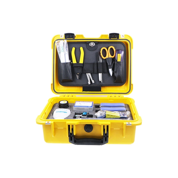
The fiber optic ST connector nails this with a simple but brilliant design. At its core, the ST connector's design is all about ensuring a precise and unshakeable connection between two optical fibers. Your data is just pulses of light zipping through hair-thin glass strands. The bayonet-style coupling system they utilize ensures a safe connection can be established that won't fail easily, making them excellent for situations where reliability is essential. For optimal connectivity performance, invest in a Fiber Optic Inspection and Cleaning Kit for your installation team. Do not use acetone for cleaning.
[PDF Version]
-
How to use fiber optic access switch for monitoring
Want to extend your IP cameras, wireless access point, or network devices over 1 kilometer? In this video, we walk you through a real-world fiber optic installation for a logistics client who needed to monitor a remote yard. We cover everything — from choosing fiber . A Network TAP (Traffic Access Point) is a hardware device that creates an exact copy of all data flowing across a network link, allowing for passive network monitoring and analysis without interfering with the actual traffic. A fiber optic TAP enables uninterrupted data transmission by connecting. In the realm of fiber optics, optical switches are indispensable for their ability to manage the flow of light signals, ensuring the agility and efficiency of network traffic. With the scalable distances allowed by fiber optics, our interlock switches can be networked across a wide area while utilizing existing standard communication fiber networks. An advanced fiber optic sensing platform that is flexible and. strict privacy laws and typically follow ETSI or CALEA standards. TeliSwitch AFMS system enables monitoring of all kinds of optical networks with central optical testing devices, such as OTDR.
[PDF Version]
-
What is a fiber optic aggregation switch called
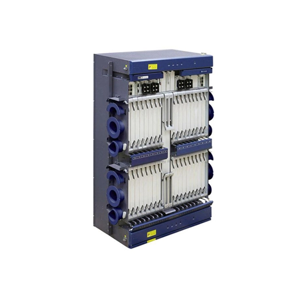
An SFP aggregation switch is a network device that consolidates network connections from various sources and transmits the aggregated traffic to the appropriate destinations. They are built to handle large amounts of data flowing through them without interruptions over long distances. So, what exactly are fiber aggregation points? They are the centralized hubs where multiple fiber optic cables intersect. It also enables easy expansion by simply adding more fiber or network switches. Long-distance installations often require fiber optic cables to connect different sites because of. Aggregation switches act as central hubs, enabling multiple devices within a network to connect and exchange data. They offer improved bandwidth management, increased network capacity, and enhanced network performance.
[PDF Version]
-
Does the aggregation switch need power
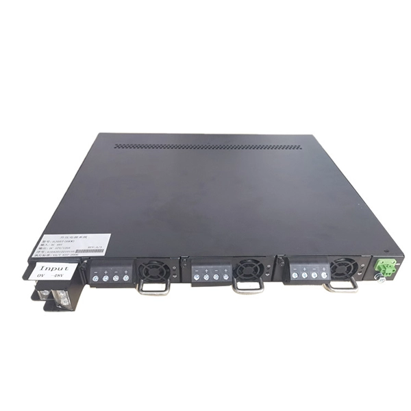
Redundancy capabilities are crucial for ensuring network security and are among the key factors that network administrators need to consider when choosing an aggregation switch. For an Aggregation Switch, having redundant power is essential. An access switch's job is straightforward: get devices onto the network and pass their traffic upstream. They need fewer ports, but those ports run at much higher speeds (10 Gbps, 25 Gbps, or 40 Gbps) to handle the combined traffic of. An aggregate switch is a high-capacity network switch that consolidates connections from multiple access switches, acting as a central point for managing network traffic and providing enhanced bandwidth capabilities.
[PDF Version]
-
How is the core switch connected to the aggregation point
A pair of core switches joins the aggregation switches together using high-speed, Layer 3 links and multiple equal-cost multipath (ECMP) routing. It provides a high-speed connection between different distribution layer devices. The core layer runs an interior. With the Fortinet solution for integrated networking using FortiLink, the core layer always comprises a set of two to four FortiGate devices and two very high-speed FortiSwitch units, which support a large number of 100-GbE and/or 40-GbE ports with enough capacity to grow the links between them and. Switch aggregation, also known as link aggregation or trunking, is a method used in computer networking to combine (aggregate) multiple network connections in parallel. This arrangement increases throughput beyond what a single relationship could sustain, offers redundancy in case one of the links.
[PDF Version]
-
How to check the access switch in the aggregation process
Run the display netconf connect-status command to check the NETCONF configuration on the switch, including the connection status between the switch and iMaster NCE-Campus. Log in to the device CLI to view the Eth-Trunk interface information. Manually add information about aggregation and access switches to the site. Choose Design > Site Design > Device Management > Device. The ESNs of switches, APs, and WACs must be entered into the site to. When LACP (Link Aggregation Control Protocol) or static LAG (Link Aggregation Group) is not functioning properly, common troubleshooting steps and checkpoints include: 1. Check Physical Connections: Ensure that the aggregated ports are correctly connected to the corresponding devices, with no loose. This document explains how to configure LAG on a switch through the Command Line Interface (CLI). If you are unfamiliar with terms in this document, check out Cisco Business: Glossary of New Terms. LAG combines two or more ports to increase capacity and reliability. Aggregating multiple links between physical interfaces creates a single logical point-to-point trunk link or a LAG.
[PDF Version]
-
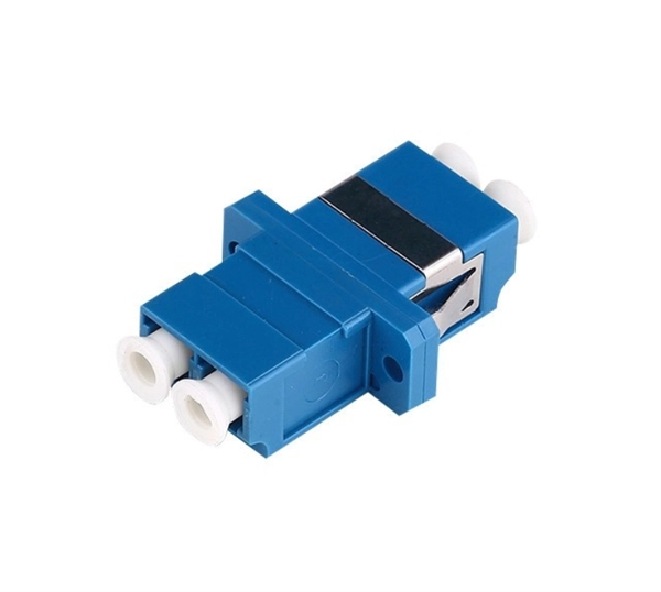
How to connect fiber optic cable to a panel light switch
Connect the fiber optic cable: Attach the fiber optic cable's connector to the transceiver module on the switch. Make sure the connector type (e. This article will guide you through the necessary tools, materials, and methods on how to connect fiber optic cables effectively. Connecting a fiber optic switch involves several steps, ensuring compatibility between the switch's ports and the fiber optic cable. Due to slight structural differences, the LC connector uses a latch mechanism, the FC connector uses a threaded screw mechanism, the SC connector uses a push-pull with latch mechanism, and the ST. This comprehensive guide equips you to be your own technician, exploring the intricacies of fiber optic technology, the steps involved in the installation process, the tools required, and valuable tips to ensure a successful setup. Before connecting any fiber cable, you need to assemble the proper preparation tools: With the right tools in hand, follow these key steps to achieve reliable fiber connections: 1. Strip and Clean Fiber Ends.
[PDF Version]
-
How many cores are typically in an optical fiber splice closure
Fiber splice enclosures protect delicate fiber optic connections from moisture, dust, and physical damage. They come in different types for various environments (indoor/outdoor), sealing methods (mechanical/heat shrink), and core capacities (12-96 cores). com are available from typical 12 core closures to 500 cores or more. The right choice depends on installation. The vertical dome fiber optic closure is a widely used solution for underground and direct burial applications. Ideal for network expansion and distribution, it securely houses fiber cables while. Dome Type 3 Port Fiber Optic Splice Closure Heat Shrinkable FOSC, LW-FOSC-DH-24A-3 Description: Fiber Optic Splice Closure, also named Fiber Optic Joint Enclosure, is [. ] Dome Type 4 Port Fiber Optic Splice Closure Mechanical Sealing FOSC, LW-FOSC-DM-48A-4 4 round ports 12 cores/tray, 6 Slots/tray. Mechanical fiber optic dome closure for max.
[PDF Version]
-
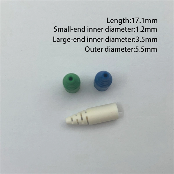
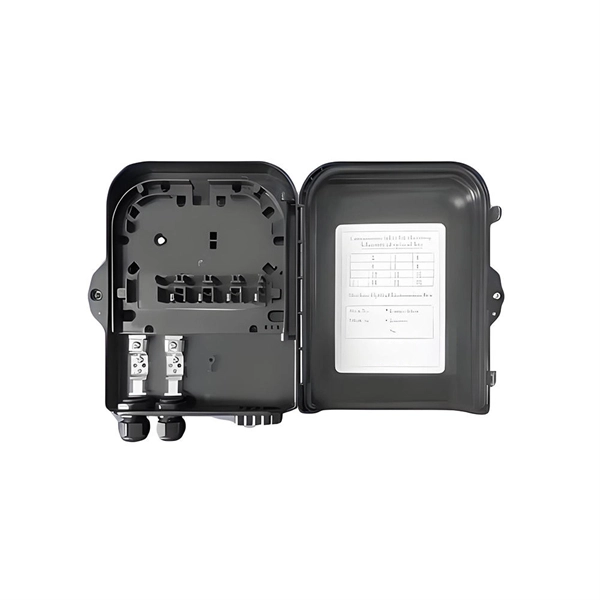
How to connect an eight-core fiber optic cable to a terminal box
Extending the fiber through the box makes use of a cable entry gland. Fasten the cable to the clamps or ties to assure the cable is immovable. Remove the cable jacket and buffer coating. The fiber termination box is an interface between the fiber cable from the line side and the pigtails to be passed to the fiber distribution frame. Covers mounting, splicing, routing, labeling, and testing for indoor/outdoor use. Installing a fiber optic termination box is one of those jobs that looks simple on paper, but it's easy to do poorly in the field. html ) in detail, including characteristics and applications. Labeling tape: Use this to label the fiber optic cables for. Connecting a fiber optic cable properly ensures optimal network performance and reliability: Router Connection: Begin by inserting the fiber cable into the router. Ensure the connector type matches the port on the router.
[PDF Version]
-
How to Choose an Italian Fiber Optic Sensor
Use this fiber-optic sensors buying guide to compare major types, define selection criteria, and find suppliers: Professional purchasing of high-value photonics products is a substantial responsibility, where a structured decision-making process is essential. RP Photonics. Fiber optic sensors are pivotal components in modern sensing technology, underpinning high-precision detection across critical industries from industrial manufacturing to infrastructure monitoring. OST is able to propose the most suitable technology for all measurement requirements, developing custom solutions for every. When installation space is extremely limited or the objects to be detected are tiny, fiber-optic sensors are the ideal solution. Detection in Narrow Locations The small sensing section and flexible Fiber Unit cable enable a Fiber Sensor to. Our global manufacturing network for fiber optic sensors in Ayabe (Japan), Shanghai (China) and Nufringen (Germany) focuses on continuously optimising methods for small and large volume production, applying stringent quality control procedures, and expanding production portfolio and flexibility to.
[PDF Version]
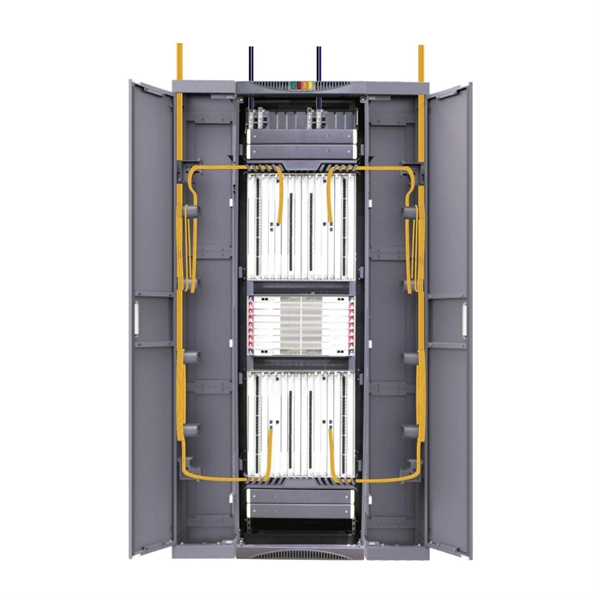
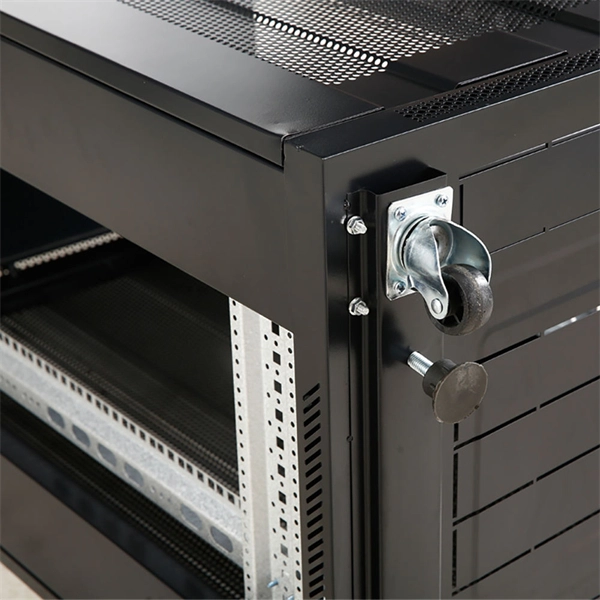
Telecom Racks & Cabinets
19-inch racks, wall-mount cabinets, open frames with high load capacity and seismic rating.
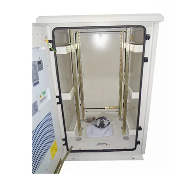
Outdoor Climate Cabinets
IP55/IP66 outdoor enclosures with integrated cooling/heating, -40°C to +55°C operation.
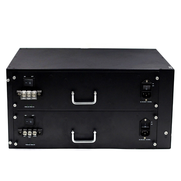
Smart PDUs & Power Distribution
Intelligent PDUs with remote monitoring, per-outlet switching, and environmental sensors.
Shelters & Network Cabinets
Prefabricated telecom shelters, emergency comms shelters, and network cabinets with cable management.