Digital Optical Module Block Diagram
Digital Optical Module Block Diagram Trigger (2) Pulser 10b
PC817 Optocoupler Module User Guide | Wiring & Setup
Complete PC817 optocoupler isolation module guide. Covers 3.6V–30V wiring, jumper settings, resistor selection, Arduino/ESP32/PLC hookup & troubleshooting.
How a Tiny, Low-Power MCU Meets the Needs of an Optical Module
The following is the internal block diagram of a typical optical module: Figure 2: Typical Optical Module Internal Block Diagram. As shown in the previous figure, the MCU manages many
Schematic view of the main components of an optical module: (a)
The key element of many deep-sea Cherenkov detectors is the so-called "optical module", a pressure-resistant glass sphere that contains photomultipliers, which are optically coupled to the...
400G Optical Module Block Diagram
Interactive block diagram illustrating multiple Microchip components used in an optical module design
Optical Encoder Wiring Diagram
High Performance Optical Encoder Module With Disk. Optical Encoder Types Interfacing Differences Its Applications. General Diagram Of An Optical Encoder Scientific. Electronics Project.

Product Drawings Resource Center | Optical Communications | Corning
Corning provides a variety of optical hardware component drawings. Choose from two-dimensional and isometiric product drawings in PDF, DXF, VSS formats, and Building Information Modeling (BIM)
Arduino Tutorial: HY-M154 / 817 / PC817 Optocoupler Module
Complete PC817 optocoupler isolation module guide. Covers 3.6V–30V wiring, jumper settings, resistor selection, Arduino/ESP32/PLC hookup
Overview of the Development of Fiber Optic Transceivers
Fiber optic transceiver, also called optical module, is used to realize the conversion between electrical and optical signals. It is the core device for connecting communication equipment
How a Tiny, Low-Power MCU Meets the Needs of an
The following is the internal block diagram of a typical optical module: Figure 2: Typical Optical Module Internal Block Diagram. As shown in the
Optical module design resources | TI
View the TI Optical module block diagram, product recommendations, reference designs and start designing.
Arduino Tutorial: HY-M154 / 817 / PC817 Optocoupler Module
This tutorial gives an introduction to the HY-M154 / 817 optocoupler module. Moreover, a simple application is programmed that shows how to wire and how to program an Arduino when
Telecom Racks & Cabinets
19-inch racks, wall-mount cabinets, open frames with high load capacity and seismic rating.
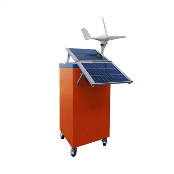
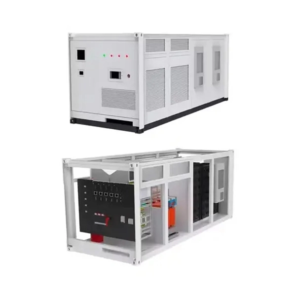
Outdoor Climate Cabinets
IP55/IP66 outdoor enclosures with integrated cooling/heating, -40°C to +55°C operation.
Smart PDUs & Power Distribution
Intelligent PDUs with remote monitoring, per-outlet switching, and environmental sensors.
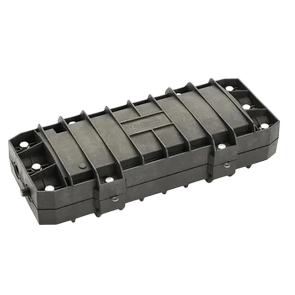
Shelters & Network Cabinets
Prefabricated telecom shelters, emergency comms shelters, and network cabinets with cable management.