-
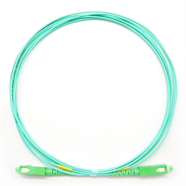
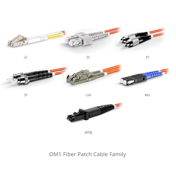
Dual-core fiber optic patch cord manufacturing process
Explore the complete manufacturing and testing process of fiber optic patch cords, including polishing, assembly, and IL/RL testing. Discover how Gcabling ensures consistent quality for high-performance connectivity. This guide unveils the complete production workflow compliant with **IEC 61754** and **Telcordia GR-326-CORE** standards, featuring proprietary quality control methods. Its main purpose is to form a flexible, high-performance link between active equipment and optical networking devices such as patch. This guide offers a comprehensive overview of what it means to be a fiber patch cord manufacturer, their operations, capabilities, and quality assurance processes. A fiber patch cord manufacturer is a specialized factory focused on producing high-quality optical fiber cables, including single-mode.
[PDF Version]
-
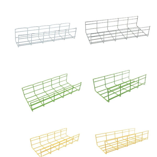
Cable tray manufacturing process in the workshop
The manufacturing process of cable trays mainly includes cutting, punching, bending, and welding. Firstly, cut the raw materials according to the design drawings to ensure accurate dimensions. Understanding the. As a crucial component of power and electrical engineering, cable trays have complex production processes involving multiple stages. The production process of cable trays, from design to finished product, usually includes the following key steps: Design and Planning Stage The production process of. Cable tray manufacturing relies on a coordinated production line of specialized machines: a roll forming line shapes the profile, a CNC press brake handles secondary bending, a punch press creates mounting holes and ventilation slots, and a shearing line cuts the finished tray to length. This video gives you a complete walkthrough of our cable tray production workshop, where raw steel is transformed into reliable cable management systems through advanced technology and skilled craftsmanship. more Welcome to our core manufacturing space. Understanding these aspects is.
[PDF Version]
-
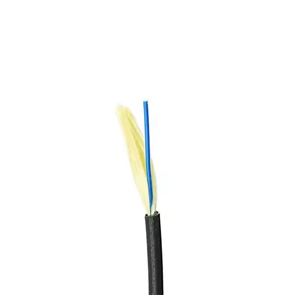
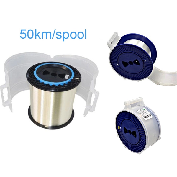
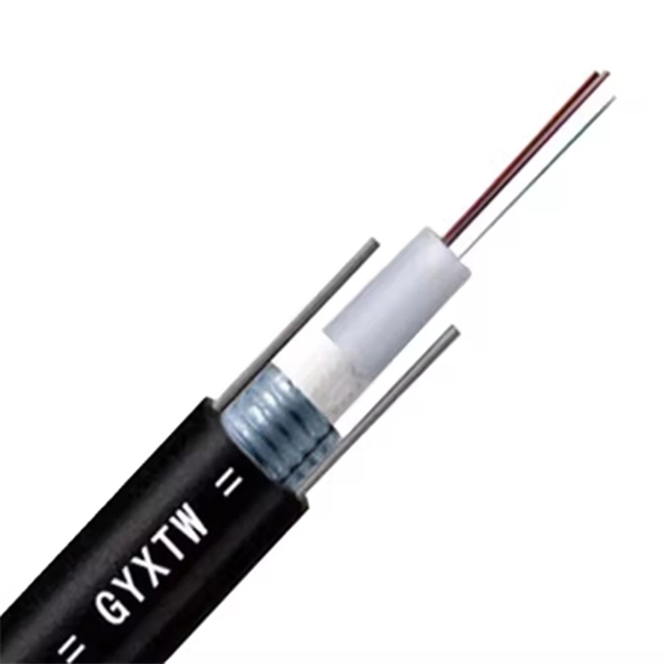
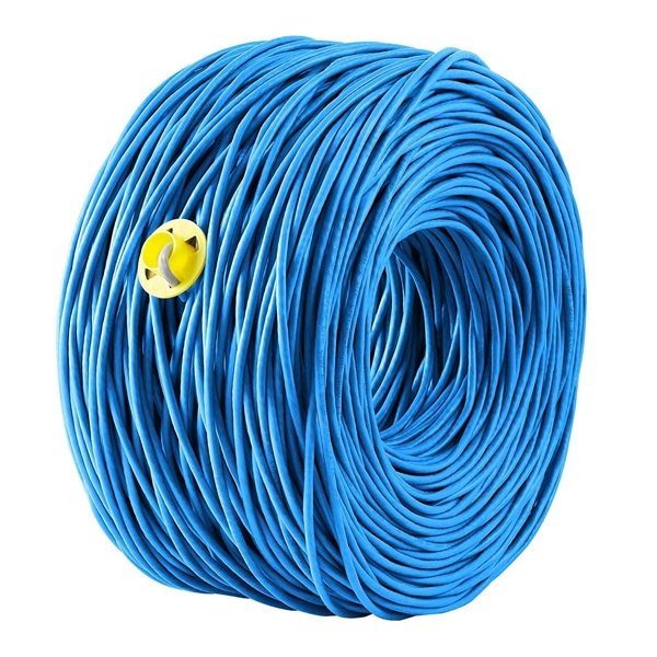
Communication Optical Cable Manufacturing Process
Fiber optic cable is made by drawing ultrapure glass or plastic into hair-thin strands called optical fibers, coating them in protective layers, and then bundling and jacketing them into a finished cable assembly. Fiber optic cables are the backbone of today's high-speed internet, telecommunication systems, and data transfer technologies. Unlike traditional copper cables, fiber optic cables use light signals to transmit data, which allows them to carry large amounts of information at extremely high speeds. Short summary: The journey from a grain of sand to a high-speed fiber optic cable is a marvel of modern engineering. This guide unveils the intricate, multi-stage manufacturing process, showcasing the precision and technology required to create the backbone of global communication and highlighting. Single-mode fiber represents the pinnacle of long-distance optical transmission technology. With its precisely engineered small core diameter, SMF enables crystal-clear data transmission across vast distances. Preform Fabrication – The Foundation of Optical Fiber 1.
[PDF Version]
-
Mongolian Aluminum Alloy Explosion-proof Distribution Box Manufacturing Process
Surface finishing ensures corrosion resistance and aesthetics. Galvanization / Painting: Depending on customer requirements. Salt Spray Test: Conducted to verify long-term outdoor durability. Assembly & WeldingThis manufacturer and trader primarily exports to Trinidad and Tobago, Mongolia, and the UAE. The positive review rate is 100. Minmile's explosion-proof products focus on the risks of dust and flammable gas explosions in the food industry, adapting to the safety needs of the entire production process. Its core products are designed for processing scenarios such as flour, sugar powder, and milk powder, balancing. Alloy Industry Co. It is much lighter than cast iron, so it makes the. At E-abel, we combine advanced production equipment, strict quality control, and international certification standards to provide high-performance distribution boxes tailored for global markets. Applicable to Zone 1 and Zone.
[PDF Version]
-
Industrial Switch Shell Manufacturing Process
Electric switch manufacturing involves several key processes, including design, material selection, fabrication, assembly, and testing. Design engineers create blueprints for switches based on functional requirements and customer specifications. It's beyond "just a grey enclosure" Revolution Slider Error: The param Slider Width should not be empty. Switches are used in a variety of applications to control the flow of electricity, such as in lighting, heating, and cooling systems. by Greg Carter, Electrical Marketing If you're responsible for specifying or installing custom electrical switchboards, knowing what happens behind the scenes helps you make. From in-depth comparisons like Injection Molding vs. 3D Printing to advanced techniques like overmolding, discover the right technology for your project. In this video, we'll walk you through the 10 essential. Build Structure with Expert Welding and Assembly In our switchboard manufacturing facility, skilled technicians weld and assemble the fabricated steel into a rugged, dimensionally accurate enclosure.
[PDF Version]
-
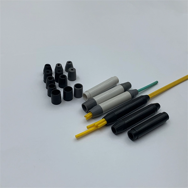
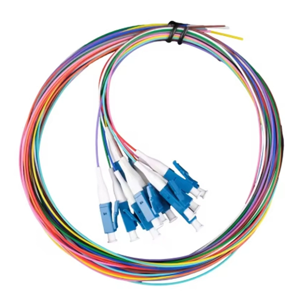
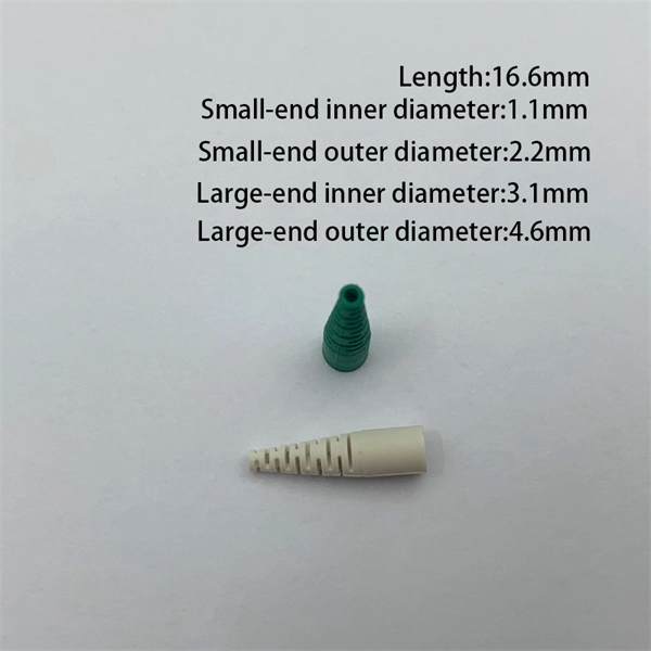
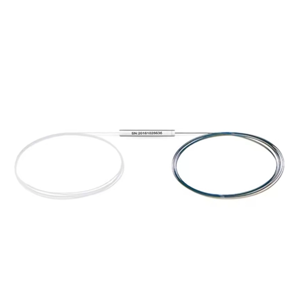
Price of Dual-Core Pigtail Manufacturing Process
The production process of optical fiber pigtails involves several essential steps to ensure the quality and performance of the final product. A pigtail fiber is a short, single-strand fiber optic cable with a factory-terminated connector on one end and bare fiber on the other, used to connect optical cables to network equipment or splice with other fibers. Here's a general overview of what such a production line might include: Fiber Optic Cables: Opting for the right fiber models (single-mode vs. Connectors: Different. Our Fiber Optic Patch Cord Production Line equipment includes everything needed to manufacture high-quality patch cables and pigtails: from cable making machines and pneumatic crimpers to precision polishing fixtures and IL/RL test stations. To ensure quality, perform thorough evaluations of suppliers, validate their certifications, inspect production facilities, and request product samples.
[PDF Version]
-
High-precision customization process for dense wavelength division multiplexers for subway applications
Here, we develop a novel design approach that co-optimizes inverse-designed wavelength division multiplexers and distributed Bragg gratings to achieve ultra-low crosstalk without compromising insertion loss. By utilizing thin-film technology in the development and manufacturing of our DWDM. 📦 For purchasing, use the RP Photonics Buyer's Guide for wavelength division multiplexing. It provides an expert-curated supplier directory, buyer-focused technical background information, and structured selection criteria to support professional procurement decisions. In one embodiment, an array of micro membranes and an array of cavities for optical fibers are etched in a substrate.
[PDF Version]
-
Customization Process for Anti-Certificate Tracking of ESCON Connectors for Cloud Computing
This publication describes the Enterprise Systems Connection (ESCONTM) Channel-to-Channel adapter and the Fibre Connection (FICONTM) Channel-to-Channel adapter. A technical change to the text or illustration is indicated by a vertical line to the left of the change. Manual #certificate tracking is time-consuming, error-prone, and unsustainable in today's hybrid, distributed environments. With just API. Active Directory Certificate Services (AD CS) attack surface is pretty well explored in Active Directory itself, with *checks notes* already 16 “ESC” attacks being publicly described. Hybrid certificate attack paths have not gained that much attention yet, though I have come across several hybrid. ESCON replaces the previous S/370 parallel channel with the ESCON I/O interface, supporting additional media and interface protocols. Prizm supports conversion of native FICON (FC) to native ESCON. The Quantum Computing Cybersecurity Preparedness Act (H. 7535), signed into law in 2022, requires agencies to prepare now to implement Post-Quantum Cryptography (PQC). They are commonly used to encrypt and sign data, authenticate users and devices, and secure network.
[PDF Version]
-
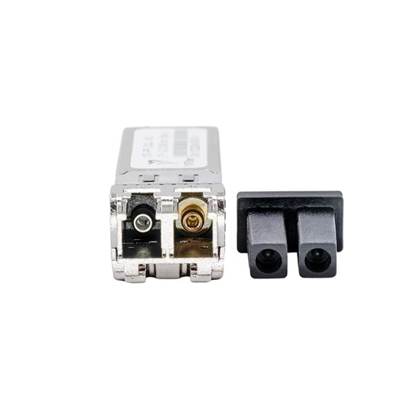
Customization Process of 100G Air-Cooled Switches vs Traditional Cables
This post serves as your practical guide, breaking down the essential components and considerations for how to build a 100G data center. Increased adoption of high performance servers coupled with applications using higher bandwidth is accelerating the need for dense 100 Gigabit Ethernet switching in both leaf and spine tiers of modern networks. As discussed in our previous post “When to Upgrade to 100G“, the relentless growth of data traffic, fueled by cloud computing, video streaming, real-time. The Spine-Leaf architecture has emerged as the de facto standard for 100G data centers due to its ability to deliver ultra-low latency, non-blocking throughput, and linear scalability.
[PDF Version]
-
Customization Process for Low-Loss SMA Connectors Used in Supercomputing Centers
This guide walks through the practical decision-making process: length selection, loss estimation, male-to-female direction mapping, bulkhead use, and when right-angle ends help more than they hurt. Through extensive S -parameter and time-domain reflectometry (TDR) measurements conducted on various SMA connector constructions, this study aims to evaluate the performance and impact of SMA connectors on signal integrity. Results reveal insights into the comparative performance of different SMA. Pin Flight Times across Packages 1. Package Migration from UltraScale to UltraScale+ FPGAs 2. Power Supply Voltage Levels and VCCINT_IO Connection 4. Transceiver Changes from. This article breaks down the role of low-loss SMA connectors, explains what causes signal loss, and provides practical tips for selecting and installing the right RF components to ensure clearer transmission and more accurate measurements. FAQ 1: Why Is Low Loss So Critical in RF Transmission?A sma to sma cable seems trivial, but at higher frequencies—5 GHz Wi-Fi, 3–6 GHz lab test bands, or 5G-NR sub-6 setups—the wrong choice can eat directly into your link budget.
[PDF Version]
-
Customization Process for Smart City E2000 Connector Remote Monitoring Type
This guide helps network engineers and field teams design and validate fiber links and transceiver choices that survive heat, dust, and long maintenance cycles. By checking this box I confirm that I have read the Privacy. The correct installation of E2000 connectors is crucial for the long-term performance and reliability of fiber optic networks. E2000 is an optical fiber plug connector, with a 1. 25 mm ferrule, available for both single mode and multi-mode applications, featuring a. e robust design. Variants: E-2000 /PC and E-2000 /APC.
[PDF Version]
-
Intelligent Customization Process for Fiber Optic Cable Junction Boxes in Distribution Network Automation
This report discusses the application and research of the Fiber Optic Distribution Box (FDB), systematically explaining its basic concepts, functional structure, operating principles, application scenarios, technical standards, development trends, and practical challenges. Custom distribution units are specially designed enclosures that house and protect electric and fiber facilities inside them. APT provides services of. Transform your fiber enclosure vision into reality with our end-to-end OEM/ODM solutions – precision-engineered for mission-critical telco deployments. Beat project deadlines with our streamlined manufacturing: High-volume output, rapid sample-to-production turnkey, and 99. Each series has different types to fit your needs. Having trouble with unique connectivity challenges? Explore MellaxTel's custom solutions for. Fiber optic distribution boxes play an essential role in modern telecommunications infrastructure, enabling smooth and reliable connections for fiber optic networks in various applications, including FTTH (Fiber to the Home) and FTTX (Fiber to the X) deployments.
[PDF Version]
-
Custom Process for 850nm Hollow-Core Optical Fiber in Mining
This webinar explores the complete hollow-core fiber manufacturing chain and the Nextrom machinery that enables it. Beginning with preform manufacturing systems, it examines equipment designed to produce high-quality structures for hollow-core geometries. Compared to. M2 Optics offers a large portfolio of specialty optical fibers and components for high-speed aerospace, photonics, medical, automotive, and other advanced communications applications. But moving from prototypes to stable, repeatable production requires dedicated manufacturing systems. This. Hollow-core optical fibers (HCFs) have unique properties like low latency, negligible optical nonlinearity, wide low-loss spectrum, up to 2100 nm, the ability to carry high power, and potentially lower loss then solid-core single-mode fibers (SMFs). 6 dB/km and phase birefringence of 1.
[PDF Version]
-
Installation process of the pigtail channel
This guide, led by James Adams of ABR Electric, walks you through how to pigtail wires properly for a safe and reliable electrical system. 📌 What You'll Learn in This Video: ✅ What is Pigtailing? (0:22) – Why and when you should pigtail wires. ✅ Common Wiring Mistakes (0:36) – Avoid. The technique known as pigtailing involves using short lengths of wire to bridge the main circuit conductors and the device terminals, isolating the receptacle from the continuous circuit path. This method is the standard for electricians, ensuring a more stable and serviceable electrical. Pigtail connections are most frequently used to ground a switch or electrical outlet and for electrical devices that need to connect to multiple circuit wires. Professionals often prefer this method because it isolates issues, protecting downstream circuits from cascading failures. Why does this matter? Modern systems demand precision.
[PDF Version]
-
Fiber Optic Switch Construction Process
Constructing a fiber optic network involves several key phases: field data collection 2, make-ready engineering 3, installation 4, and rigorous quality testing 5. Each phase has unique challenges and requirements that must be addressed to ensure a high-performance network. From the initial site survey to the final fiber to the home (FTTH) connection, every stage requires careful planning, coordination, and. What is “fiber optic network design?” Fiber optic network design refers to the specialized processes leading to a successful installation and operation of a fiber optic network. It requires obtaining permits and rights-of-way. It includes first determining the type of communication system (s) which will be carried over the network, the geographic layout (premises, campus, outside. Geospatial Net is your one-stop shop for design, planning, survey, as-built documentation, GIS and CAD system design, data analytics, and system integration. Our expertise ensures properly planned network, and up to date documentation for the fiber infrastructure, making future maintenance.
[PDF Version]
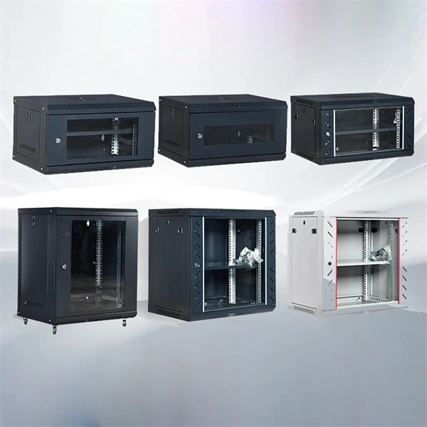
Telecom Racks & Cabinets
19-inch racks, wall-mount cabinets, open frames with high load capacity and seismic rating.
Outdoor Climate Cabinets
IP55/IP66 outdoor enclosures with integrated cooling/heating, -40°C to +55°C operation.
Smart PDUs & Power Distribution
Intelligent PDUs with remote monitoring, per-outlet switching, and environmental sensors.
Shelters & Network Cabinets
Prefabricated telecom shelters, emergency comms shelters, and network cabinets with cable management.