Fiber Optic Cabling Loss Limits Explained – Trend Networks
Learn about fiber optic cabling loss limits & how to calculate them. Gain insights from experts on acceptable loss for cabling projects & explore the standards.
What is negative loss in fiber?
What is negative loss in fiber? Negative loss is caused by the joining of two fibers with different backscatter coeffecients. A higher backscatter coefficient, on the second half of the
Fiber Optic Link Loss Budget calculator: Get Signal Loss
Fiber Link Loss Budget Calculator: Test optical power, margins & distances. Check dB losses from connectors & splice to ensure reliability.
Interpreting OTDR Trace Results
A small dip or step-down in the trace signals the presence of a fiber splice, where two fibers have been fused together. Since fusion splicing is designed to create minimal loss, a properly
How to Achieve Lowest Fiber Splicing Loss
Miss alignment and other splicing process factors can increase fiber splicing loss. Splice loss as high as 0.04dB is observed with even same MFD and geometry identical fibers.
Understanding Splice Loss: Causes and Fixes – DBtek
Excessive splice loss is avoidable with proper preparation, equipment maintenance, and attention to environmental factors. DBtek''s GT40 and GT60 splicers, combined with proper technician practices,
5. Splice Loss Estimation and Fiber Imaging
Loss estimation is most commonly applied to single-mode fiber (SMF) since SMF typically exhibits higher splice loss than multimode fiber (MMF), and SMF communication systems are typically less
Fiber Optic Splicing: Examining the Factors that Affect Splice Perform
Learn the the intrinsic and extrinsic factors that can impact fiber optic splice performance and how you can create the best fiber optic network.
Fiber Link Loss Budget Calculator
Corning''s link loss budget calculator will calculate your total link loss and tell you if your system falls within Corning''s recommended guidelines.
Factors affecting fiber splice loss and how to reduce it
Fiber splice loss is caused by core mismatch, contamination, and misalignment. Reduce loss with proper cleaning, alignment, and splicing techniques.
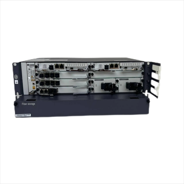
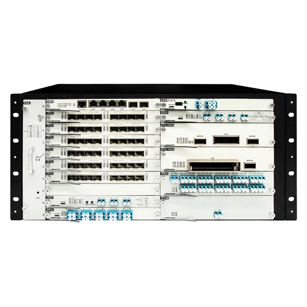
Telecom Racks & Cabinets
19-inch racks, wall-mount cabinets, open frames with high load capacity and seismic rating.
Outdoor Climate Cabinets
IP55/IP66 outdoor enclosures with integrated cooling/heating, -40°C to +55°C operation.
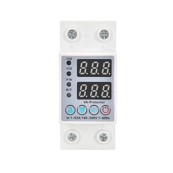
Smart PDUs & Power Distribution
Intelligent PDUs with remote monitoring, per-outlet switching, and environmental sensors.
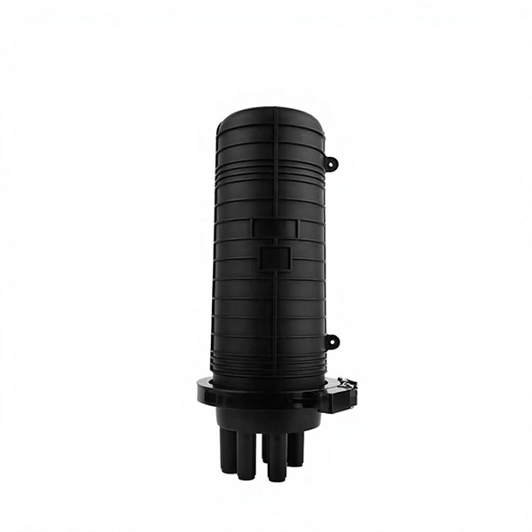
Shelters & Network Cabinets
Prefabricated telecom shelters, emergency comms shelters, and network cabinets with cable management.